


BRADFORD WHITE CORP.
Page 4
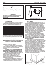
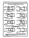
temperature may be less than 120°F, such
as in-floor radiant systems, snow melt
systems or other systems where a “cold
start” is expected frequently due to
thermostat setbacks, etc. See Figure 11.
b. Any system where the temperature rise
across the heat exchanger is above 30°F
(see Section 5 and Figure 7).
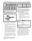
2. Combustion air grates for openings sized in
accordance with Section 3.1.
3. Field interlock wiring for any motorized
combustion air louvers to ensure the boiler does
not fire if motorized louvers do not open.
4. A suitable non-combustible base if installed on a
combustible floor (see Section 2.3.2)
1.5.3 Diagnostic Tools
The following materials are needed to verify
correct installation:
1. Gas manometer to verify gas pressure
2. Strap-on, digital or infrared thermometer to
check temperature rise across the heat exchanger.
3. Suggested: Draft gauge and combustion test
equipment.
1.6 Specifications
1.6.1 General Specifications
1. Installation Location:
Certified for use in Indoor Applications only
2. Minimum Clearance From Combustible
Material:
See Table 1 in Section 2.3.1.
3. Supply Gas Type:
Certified for use with Natural Gas and LP Gas
4. Gas Pipe/Boiler Gas Valve Connection:
Nat LP
50-225 ½" NPT ½" NPT
5. Inlet Gas Supply Pressure:
Minimum Maximum
Natural Gas: 5.5" WC 10.5" WC
LP Gas: 10.0" WC 13.0" WC
6. Water Pipe/Boiler Connection:
1¼" NPT
7. Water Flow Rate:
See Table in Section 5.2
8. Pressure Relief Valve:
30 PSI
9. Recommended system pressure:
12 PSI
10. Exhaust Vent Connection Size:
50 4" Diameter
75-100 5" Diameter
125-160 6" Diameter
225 7" Diameter
11. Electrical Supply:
115 Volts AC
12. Modification of Boiler for High Altitude:
Brute Mini Boilers are normally shipped from the
factory in the low altitude (sea level) operational
configuration. When requested, the boilers can be
configured and shipped for higher altitudes. For
field conversions to change altitude
configurations, conversion parts are available
from. For more information or call the Customer
Service Department.
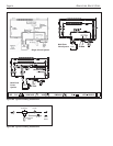
1.6.2 Dimensions
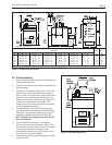
See Figure 1 for a diagram showing the boiler’s
exterior dimensions and dimensions to critical
connections on the boiler.
SECTION 2.
Installation Instructions
2.1 Introduction
WARNING
Improper installation or maintenance can cause
nausea or asphyxiation from carbon monoxide in
flue gases which could result in severe injury, or
death.
AVERTISSEMENT
Une installation ou un entretien in adéquat peut
causer la nausée ou l’asphyxie en raison du
monoxyde de carbone présent dans les gaz de
combustion et même entrainer des blessures
graves ou la mort.
Install the Brute Mini boilers and vent dampers in
accordance with the procedures in this manual, local
codes and ordinances, and in accordance with the
latest edition of the appropriate national code (see
Section 1.3 “Codes and Standards”).
All gas-fired products require correct installation
to assure safe operation. The requirements for boilers
include the following:
1. Field assembly
2. Appropriate site location (clearances) and
flooring
3. Sufficient combustion and ventilation air
4. Properly sized gas meter and piping
5. Proper electrical wiring (if required)
6. Adequate water flow
This manual provides the information needed to
meet these requirements. Review all application and
installation procedures completely before continuing
the installation.
NOTE: The Brute Mini boiler is approved for indoor
installation only.