


6
SECTION III: GENERAL INFORMATION
FEATURES
This water heater contains the following features:
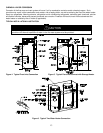
MAIN POWER ON/OFF SWITCH – The front panel of this water heater has a lighted ON/OFF switch, which is illuminated
when the main power is turned on to indicate power to the water heater.
COMBUSTION SYSTEM – This water heater is equipped with a self-compensating negative pressure pre-mix combustion
system. As the blower operates, air is drawn in through the air intake and into a venturi, which pulls gas from the gas
valve. The gas and air is then mixed in the combustion blower and sent through the transition tube into the burner. The
Direct Spark Ignition System (DSI) then ignites the gas/air fuel mixture to produce flue products (combustion). The flame
sensor signals the ignition control board (described below), that a flame is present.
HONEYWELL INTEGRATED CONTROL – Consists of a control board and a water heater display. An attractive digital
water heater display is on the top front of the water heater for precisely setting and displaying the temperature setpoint
and monitoring the status of the water heater. Pressing the temperature UP and DOWN buttons changes the temperature
setpoint. The temperature format may be displayed in degrees F or degrees C. The water heater display will show
diagnostic codes in the event the water heater needs servicing. The temperature readings of the tank sensor can be
monitored in Service Mode. Also in Service Mode, the display can show up to 10 previous error codes to further aid in
servicing the water heater.
The single control board has plug in wiring harnesses to reduce the chance of mis-wiring. The control board controls all
ignition, temperature, and combustion blower functions. The control board controls the combustion blower, ignition
timings, and gas valve to control the combustion system in order to maintain the desired tank temperature. The sequence
of operation is described in detail in the Diagnostic Section at the back of this Installation and Operating Instruction
Manual.
ADJUSTABLE THERMOSTAT – This water heater is equipped with an adjustable thermostat as part of the Integrated
Control System to control water temperature. Hot water temperatures required for automatic dishwasher and laundry use
can cause scald burns resulting in serious personal injury and/or death.
The temperature may be adjusted from about 70°F (21°C) to about 180°F (82°C). The thermostat was adjusted to 70°F
(21°C) before the water heater was shipped from the factory. It is recommended that lower temperatures be used to
avoid the risk of scalding. Refer to the “Warnings” and the section on SCALDING in “Section V: Water Connections”. It is
further recommended, in all cases, that the water temperature be set for the lowest temperature, which satisfies your hot
water requirements for the installation. This will also provide the most energy efficient operation of the water heater and
minimizes scale formation.
Setting the water heater temperature at 120°F (49°C) will reduce the risk of scalds. Some states require setting lower
temperatures for specific installations.
The top immersion well of the single sensor control also contains a redundant sensor for the high limit (energy cutoff).
The high limit circuit interrupts the main burner gas flow should the water temperature exceed approximately 200°F
(93°C). Error code “65” will be shown on the water heater control display if the high limit temperature has been exceeded.
Should the high limit switch activate, it must be manually reset. This should only be done by a service technician after the
cause of overheating has been corrected. Refer to the section on “Accessing Service Mode on the Display” in the
Diagnostic section of this Installation and Instruction Manual.
Contact your qualified installing contractor, service provider or manufacturer listed on the rating plate if continued high
limit operation occurs.
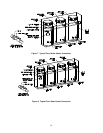
SERVICE PANEL – The service panel is located behind the service panel access cover, which is located by the exhaust
elbow near the bottom of the water heater. This panel contains a pressure switch that monitors the pressure in the
exhaust pipe in case the vent terminal becomes blocked. A collector high limit switch is used to monitor the ambient
temperature between the first pass collector and the exhaust collector. This is a manually re-settable switch. If this switch
continues to trip, please contact an authorized service agency.
LATCHES – The latches allow easy access for servicing the water heater from the top. Simply remove the two latches for
servicing and re-latch upon completion. No tools are required to obtain access to the top of the water heater.