


27
POWER VENT INSTALLATION
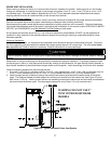
Power venting is where the indoor air is used and the exhaust is vented to the outside. Venting may be run horizontally
through an outside wall or vertically through a roof through using either 2 inch (5.1 cm), 3 inch (7.6 cm) or 4 inch (10.2
cm) diameter pipe. This water heater is supplied with a 3 inch (7.6 cm) diameter screened intake elbow and exhaust
coupling referred to as the air intake terminal and the exhaust vent terminal.
Power Vent Terminal Location:
Refer to the “Direct Vent Terminal Location” section previously mentioned to determine the proper exhaust vent location.
Plan the vent system layout so that proper clearances are maintained from plumbing and wiring.
Vent pipes serving power vented appliances are classified by building codes as “vent connectors”. Required clearances
from combustible materials must be provided in accordance with information in this manual under LOCATION OF WATER
HEATER, and CLEARANCES, and with National Fuel Gas Code and local codes.
All vent pipes and terminals are to have a 1 inch minimum clearance to combustibles. DO NOT use the placement of
insulation or other materials in the required clearance spaces surrounding the venting to combustible material unless
otherwise specified.
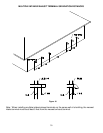
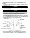
Horizontal Installation:
In a horizontal application, it is important that condensate not be allowed to buildup in the exhaust vent pipe. To prevent
this from happening, the pipe should be installed with a slight upward slope of 1/4 inch per foot. The vent system must
be supported every 5 feet of vertical run and every 3 feet of horizontal run of vent pipe length.
Stress levels in the pipe and fittings can be significantly increased by improper installation. If rigid pipe clamps are used
to hold the pipe in place, or if the pipe cannot move freely through a wall penetration, the pipe may be directly stressed, or
high thermal stresses may be formed when the pipe heats up and expands. Install accordingly to minimize such stresses.
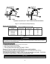
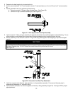
Follow the following procedure to vent through the wall:
1. Cut one 2 ½ inch (6.4 cm), diameter hole (for 2 inch (5.1 cm) diameter pipe), one 3 ½ inch (8.9 cm) diameter hole (for
3 inch (7.6 cm) diameter pipe) or one 4 ½ inch (11.5 cm) diameter hole (for 4 inch (10.2 cm) diameter pipe).
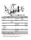
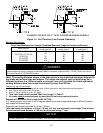
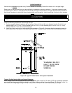
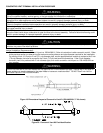
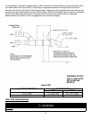
2. Use the proper cement or sealant to secure the exhaust vent terminal provided with the water heater to the plastic
pipes. The distance between the back edge of the exhaust vent terminal and the exterior wall (see Figure 15) must
be 6 inches (13.0 cm). Use the proper cement and assembly procedures to secure the vent connector joints between
the terminal and the blower outlet. Provide support brackets for every 3 feet (1.0 m) of horizontal vent.
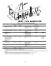
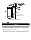
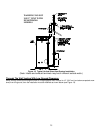
Figure 15. Typical Horizontal Power Vent System
CAUTION
Failure to properly support the vent piping with hangers and clamps may result in damage to the water heater or venting
system.
WARNING! DO NOT USE 2”
VENT WITH EF100T250/300
MODELS