


38
SECTION VIII: ELECTRICAL CONNECTIONS
WARNING
Turn off or disconnect the electrical power supply to the water heater before servicing. Label all wires prior to
disconnection when servicing controls. Wiring errors can cause improper and dangerous operation. Verify proper
operation after servicing.
All electrical wiring must be installed and grounded in accordance with local codes, or in the absence of local
codes, the National Electrical Code, ANSI/NFPA 70 and/or CSA C22.2 Electrical Code.
The water heater must be wired to a 120 VAC, 60 Hz, 15A power supply. The water heater must be wired on a separate
circuit and breaker. If a flexible line cord and plug is permitted by local code, then provide a three wire grounding type
receptacle within reach of the line cord provided on the control box. Do not plug the line cord into a receptacle that can
have the power supply interrupted by a switch that is used to control lights or another appliance.
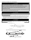
If wiring in conduit is required, cut the line cord close to the control board and make the appropriate wiring connections.
Install an electrical conduit connector on the outside jacket of the water heater. Refer to the wiring diagram for the correct
connections to each wire lead.
CAUTION
This water heater must be wired on a separate circuit. Failure to wire on a separate circuit may cause
improper operation or failure of the electrical components of the water heater. Refer to the “Electrical
Connections” section of the Installation and Operating Instructions Manual for complete instructions on
electrical wiring and connections to the water heater.
Do not energize the electric circuit before the water heater tank is filled with water.
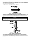
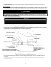
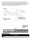
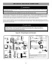
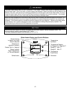
Figure 25. Wiring Diagram and Schematic
LINE IN
PRIMARY
SECONDARY
CONTROL
E-COM
1
2
3
E-COM
1
3
2
SENSE
SENSOR 1
987
6
5
4
3
21
1
2
1
2
3
4
1
2
3
3
21
120 VOLTS AC
LINE
LOAD
24V
1
2
3
M
COMBUSTION
BLOWER
PV/MV
MV
GAS VALVE
LOWER
SENSOR
& ECO
6 PIN CONNECTOR
TO PRESSURE
SWITCH HARNESS
IF ANY OF THE ORIGINAL WIRES AS SUPPLIED WITH THE APPLIANCE
105°C WIRE OR ITS EQUIVALENT.
MUST BE REPLACED. IT MUST BE REPLACED WITH 18. GA STRANDED
SI UN DES CONDUCTEURS D'ORIGINE FOURNI AVEC L'APPAREIL DOIT
NOTE:
CONNECTION DIAGRAM
WIRING DIAGRAM
CONTROL
DISPLA
Y
TRANSFORMER
120V
HIGH VOLTAGE
SPAR
K
120V
24V
24V
24V
120 VAC
BLAC
K
120 VOLTS
120 VOLTS
24 V.
WHITE
GROUND
INDUCER
41
5
2
63
BK
BK
Y
BK
O
BL
BR
W
BK
W
BL
W
GN
BK
Y
W
R
WY
M
DISPLAY
HIGH VOLTAGE
SPAR
K
SENSE
R
R
MV
GAS VALVE
M
BLOWER RELAY COIL
W
O
PV
(BOARD CIRCUIT)
5
2
P.S.
BLOWER RELAY
BLOWER MOTOR
GN
GN
R
R
GY
GY
NC
COLLECTOR
LIMIT
ECO
TSTAT
G
GND
N
L1
TOGGLE SWITCH
LIGHT
ETRE REMPLACE UTILISER UN CONDUCTEUR 18 GA STRANDED 105°C
OU L'EQUIVALENT.
GY
R
R
GY
GY
P.S. (N.C.)
COLL HIGH-LIMIT
LIMIT (N.C.)
CONTROL BOARD
W
BK