


28
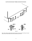
Vertical Installation:
Vertical venting must be supported every 5 feet of vertical run and every 3 feet of horizontal run of vent pipe length.
Stress levels in the pipe and fittings can be significantly increased by improper installation. If rigid pipe clamps are used
to hold the pipe in place, or if the pipe cannot move freely through a wall penetration, the pipe may be directly stressed, or
high thermal stresses may be formed when the pipe heats up and expands. Install accordingly to minimize such stresses.
CAUTION
Failure to properly support the vent piping with hangers and clamps may result in damage to the water heater or venting
system.
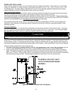
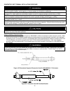
Follow the following procedure to vent through the roof:
1. Cut the necessary holes through the roof and ceiling. Cut one 2 ½ inch (6.4 cm), diameter hole (for 2 inch (5.1 cm)
diameter pipe), one 3 ½ inch (8.9 cm) diameter hole (for 3 inch (7.6 cm) diameter pipe) or one 4 ½ inch (11.5 cm)
diameter hole (for 4 inch (10.2 cm) diameter pipe).
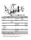
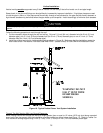
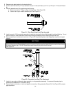
2. Install the exhaust vent and air intake plastic pipes as shown in Figure 16. Make sure that the installation meets the
local codes and/or The National Fuel Gas Code ANSI Z223.1 (Latest Edition) or CGA/CAN B149 Installation Code.
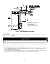
Figure 16. Typical Vertical Power Vent System Installation
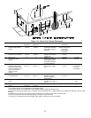
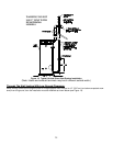
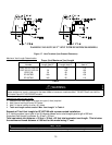
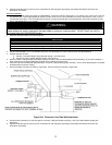
Through The Wall Venting With Low Ground Clearance:
When venting cannot exit through the wall at a height greater than or equal to 12 inches (30.5 cm) (and above expected
snow level) from the ground, then the installation must be modified as shown below (see Figure 17). Refer to Tables 3 or
4 for maximum venting lengths using 2 inch (5.1 cm), 3 inch (7.6 cm) or 4 inch (10.2 cm) diameter plastic pipe.
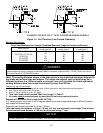
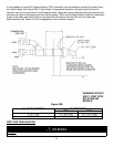
WARNING! DO NOT
USE 2” VENT WITH
EF100T250/300
MODELS