


52
SECTION XI: DIAGNOSTIC AND TROUBLESHOOTING GUIDE
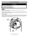
DIRECT SPARK HONEYWELL INTEGRATED CONTROL SYSTEM
SEQUENCE OF OPERATION
1. When the tank temperature drops below the temperature setpoint on the display, the control sends power to the
combustion blower for a 30 second pre-purge period.
2. At the end of the pre-purge period, the control sends high voltage through the spark cable to the spark rod to spark to
the burner. The gas valve also opens. If the burner lights, a microamp current is generated through the flame sense
rod allowing the control to detect burner flame. The sparking then ceases and the flame is monitored by the flame
sense circuit until the tank temperature reaches the thermostat setpoint and turns off the gas valve.
3. If the burner fails to light, the gas valve closes, sparking to the burner stops, and the combustion blower continues to
operate for 60 seconds to purge the heat exchanger of unburned gas. The ignition trial is repeated. The control will
make 3 attempts to ignite the burner. If the burner fails to light after the third attempt, the control enters “Soft
Lockout”, which is an idle period for 60 minutes. There will be an error code 62 or 63 shown on the water heater
display indicating that the control cycled through the maximum number of ignition retries for ignition. The control will
make another 3 ignition attempts after the 1 hour waiting period.
4. If the exhaust vent terminal should become blocked or the condensate drain becomes plugged, the exhaust vent
pressure switch will open and the gas valve closes. The combustion blower will continue to operate. An error code
29 is shown on the water heater display. Removing the blockage will resume normal operation.
5. The burner flame is monitored by the flame sense circuit and if the flame should extinguish, the gas valve closes and
the combustion blower will operate to purge the heat exchanger before making an attempt to relight the burner. There
may be 3 attempts to relight the burner before going into the Soft Lockout period explained previously.
6. The burner will continue to operate during the heating cycle until the tank temperature reaches the setpoint. The gas
valve opens and the combustion blower continues to operate for 30 seconds to purge the heat exchanger of flue
gases.
7. If for some reason, the tank temperature should exceed 200°F (93°C), then the control closes the gas valve and goes
into a “Hard Lockout” state and will not operate until reset by a qualified service person. The display will read error
code “65”, which indicates the tank high limit temperature has been exceeded. No attempt should be made to reset
the control until a service person has corrected the cause of the high limit condition. Refer to the diagnostic service
section at the end of this Installation and Operating Instruction Manual.
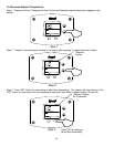
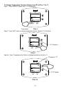
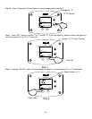
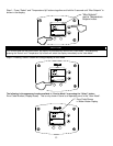
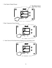
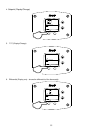
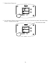
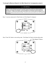
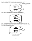
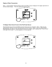
ACCESSING SERVICE MODE ON THE WATER HEATER DISPLAY (FOR SERVICE PERSONNEL
ONLY)
The display has a “Service Mode” for changing the maximum setpoint and accessing information in aiding servicing of the
water heater. This procedure is for service and installation personnel only. To enter the Service Mode, follow the steps
illustrated below:
WARNING
The following procedure is for service and installation personnel only. Resetting lockout conditions
without correcting the malfunction can result in a hazardous condition.