


19
VENTING
The venting instructions must be followed to avoid restricted combustion or recirculation of flue gases. Such
conditions cause sooting or risks of fire and asphyxiation.
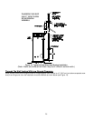
This water heater can be installed as either a direct vent system or power vent (air from inside) system. If it is
installed as a direct vent system, then the air intake and the exhaust vent are piped to the outside. If a power vented
system is used, then air is drawn from inside and only the exhaust is piped to the outside. Determine which system is
best for your application and install as described in the following sections.
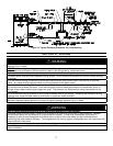
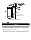
DIRECT VENT INSTALLATION
Venting may be run horizontally through an outside wall or vertically through a roof through using either 2 inch (5.1
cm), 3 inch (7.6 cm) or 4 inch (10.2 cm) diameter pipe. This water heater is supplied with a screened intake elbow
and exhaust coupling referred to as the air intake terminal and the exhaust vent terminal.
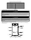
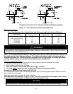
Direct Vent Terminal Location
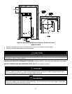
Plan the vent system layout so that proper clearances are maintained from plumbing and wiring. Before the vent is
installed, determine the vent pipe termination location as shown in Figure 11.
CAUTION
Check to make sure flue gases do not recirculate into the air intake terminal when using direct venting. If the water heater is
having service issues, flue recirculation may be a contributing factor. Even when the minimum vent terminal separation
distances are followed, recirculation may still occur depending upon the location outside the building, the distance from other
buildings, proximity to corners, weather conditions, wind patterns, and snow depth. Periodically check to make sure that flue
recirculation is not occurring. Signs of flue gas recirculation include frosted or frozen intake terminals, condensate in the intake
terminal and venting system, oxidation or white chalk material on the flame sensor or igniter shield. Correction to flue
recirculation may involve angling the intake away from the exhaust terminal, increasing the distance between them, relocating
the air intake to another side of the building, or using inside air for combustion. Check to be sure the intake and exhaust
terminals are not obstructed, especially during periods of below freezing weather.
All intake and exhaust venting components must have the same diameter size. Do not use a different size on the
intake and exhaust venting. For 2 inch or 4 inch venting, use the supplied 3 inch vent terminals. If a 2 inch vent terminal
is preferred, use 2 inch terminal Part Number 239-39831-00. This terminal is available from your supplier.
Be sure the condensate runs freely to a drain and does not accumulate inside the water heater. In cold climates,
precautions may need to be taken to insure that the condensate drain does not freeze. Make sure the condensate trap
or drain loop is installed to prevent flue gases from being discharged into the room. Refer to the Venting section of the
Installation and Operating Instructions Manual for complete instructions on venting and condensate drainage.
High levels of dust and debris such as road and construction dust, insects, and tree pollen may clog the burner resulting in
poor performance and damage to the water heater. Avoid air intake locations where debris can be created such as exhaust
ventilation hoods, gravel parking lots, and near outdoor spotlights that attract bugs. For these installations, an air intake filter
kit, part number 239-47330-00A, is available as an accessory service part from the installer of this water heater. The air intake
filter kit is not designed to filter out airborne contaminants or chemicals that may damage the water heater.
CAUTION
The vent shall terminate a minimum of 12 inches above expected snowfall level to prevent blockage of vent termination.
The horizontal centerline of the exhaust vent terminal (if applicable) must not be located lower than the horizontal
centerline of the air intake terminal if vented through the same wall.
A service drain loop must be installed in the drain tubing to serve as a condensate trap to prevent flue gases from
escaping into the room.
DO NOT position the air intake above the exhaust terminal.
NEVER locate the air intake where exhaust gases can be introduced.
WARNING
The EF100T250 and EF100T300 models are not approved for 2 inch diameter vent pipe. Venting with 2 inch pipe on
these models may result in damage to the water heater or cause an unsafe condition. DO NOT use 2 inch Vent or Air
Intake Pipe on EF100T250/300 models.