


Boiler not
operating
with a
heating /
hot water
demand
Burner
motor runs?
Burner
lights
immediately
motor runs?
230V at
solenoid coil
in purge?
Replace
control box
Replace
pump
230V at
motor?
Motor or
pump
seized?
Replace
motor
capacitor
Motor 40Ω
across
L& N?
L & N to
control box?
Control box
locks out?
Check boiler
controls &
supply
Check
connections/
replace leads
Replace
motor/
pump
Replace
motor
Replace
control box
Lockout
within 1
second?
Replace oil
pump
Oil to
pump?
Drive
coupling
broken?
Pump
produces
pressure?
Replace
transformer
Electrodes
& leads
OK?
230V at
transformer?
Spark
produced?
Lockout
after purge
before oil
solenoid
opens?
Replace
control box
Transformer
lead OK?
Photo cell
lead OK?
Disconnect photo cell,
reset lockout, burner
lights then locks out?
Stray light
on photo
cell?
Combustion
head set
correctly?
Combustion
air setting
correct?
Flame off
and
re-lights?
Nozzle
atomising
fuel?
Replace
photo cell
Photo cell
functional?
If BF
remove
burner
snorkle tube
& retest.
Lights OK?
Replace
photo cell
Replace coil
lead
230V at
solenoid
coil?
Coil lead
OK?
Boiler or
flue blocked
Reseal BF
on
reposition
Replace
control box
Replace
control box
Solenoid
operating?
2.2kΩ
across
solenoid
coil?
Pipe to
nozzle
holder OK?
Oil check
valve OK?
(if fitted)
Replace
nozzle
Replace
solenoid coil
Replace
pump
Replace oil
check valve
(if fitted)
Yes
Yes
Yes
No
No
Yes
Yes
No
No
No
No
No
Yes
Yes
No
No
Yes
No
No
Yes
No
Yes
Yes
Yes
No
Yes
Yes
Yes
Yes
No
No
No
Yes
Yes
Yes
Yes
No
No
No
No
No
Yes
Yes
Yes
Yes
Yes
No
No
No
No
Yes
Yes
Yes
Yes
Replace
lead
No
Reset air
setting
No
Reset
combustion
head
No
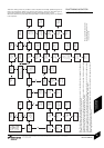
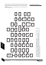
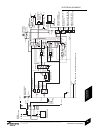
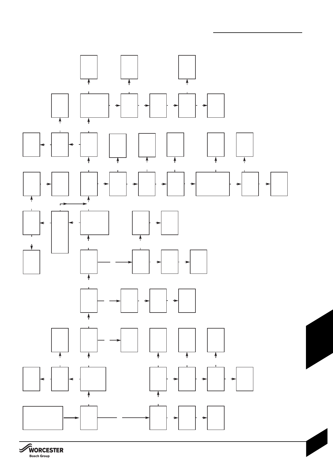
FAULT FINDING LOGIC FOR
SATRONIC CONTROL BOX
Note: This chart assumes all wiring within the control box base is correct, if in doubt check the wiring against the diagram on
the base of the control box before replacing any components.
All resistance measurements are actual measured values and some variation is to be expected, therefore measured values
should be similar to but not necessarily identical to the given values.
The operation of the photo cell can be tested by measuring the resistance across the photo cell, it should be a high resistance
(greater than 10MΩ or open circuit) in the dark and low resistance (15kΩ or less) in light.
Burners on balanced flue systems can recirculate flue products resulting in the burner cycling, if this happens check the flue
system integrity and the terminal position.
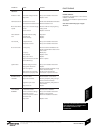
These fault finding charts are provided to assist competent and suitably qualified engineers to
locate and rectify faults. Whilst every effort has been taken to ensure the information given is
correct and complete we cannot guarantee that every eventuality has been covered.
Worcester, Bosch Group cannot be held responsible for costs incurred by persons not deemed
to be competent.
Measure all 230V tests between
Neutral (N) and the pin, wire or
terminal specified.
FAULT FINDING
INSTALLATION & SERVICING INSTRUCTIONS FOR WORCESTER GREENSTAR HEATSLAVE EXTERNAL 12/18-18/25-25/32
8 716 106 252b (07/06
46
FAULT FINDING
& DIAGRAMS