


ELECTRICS
INSTALLATION & SERVICING INSTRUCTIONS FOR WORCESTER GREENSTAR HEATSLAVE EXTERNAL 12/18-18/25-25/32
8 716 113 389b (09/07)
27
INSTALLATION
F
R
L
R
Ns
Fs
F
R
Ls
N
L
DHW
CH
ELECTRICS
1
DANGER - 230V:
ISOLATE THE MAINS ELECTRICITY
SUPPLY BEFORE STARTING ANY
WORK AND OBSERVE ALL RELEVANT
SAFETY PRECAUTIONS.
IMPORTANT: THIS APPLIANCE
PROVIDES A PERMENANT EXTERNAL
ELECTRICAL SUPPLY FOR SERVICING
AND MUST THEREFORE BE FED VIA A
CIRCUIT BREAKER INCORPORATING
EARTH LEAKAGE PROTECTION.
IMPORTANT: OBSERVE ELECTRONIC
STATIC DISCHARGE PRECAUTIONS.
DO NOT TOUCH THE PCB CIRCUITS.
WARNING: EXTERNAL EQUIPMENT
OPERATED AT 230 VOLTS SHOULD NOT
BE SERVICED OR REPAIRED UNDER
ADVERSE WEATHER CONDITIONS.
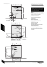
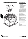
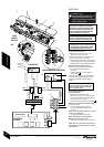
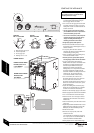
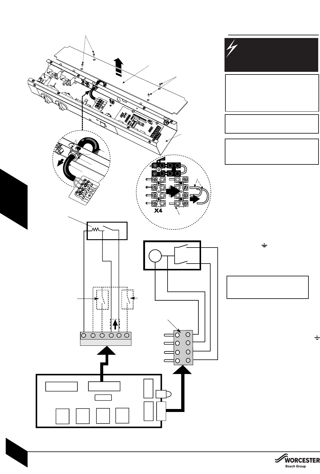
Access to 230V connections:
1Release screws (B) and remove cover
panel (C) from control box (A).
2Release screws (D) from cable clamp (E).
Pull inner clamp part (F) outwards.
Feed sufficient power cable (G) through the
cable clamp (E) and secure grip with screw (D).
Separate wires from cable end and strip to 6mm.
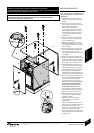
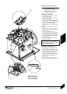
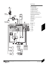
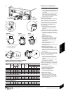
230V connections (terminal block X1):
3Connect LIVE wire (Brown) to terminal L.
Connect NEUTRAL wire (Blue) to
terminal N.
Connect EARTH wire (Green/Yellow) to
the connector .
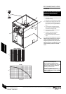
Route the power cable down the side panel and
through the service duct to the internal property
connection point avoiding any potentially hot
surfaces.
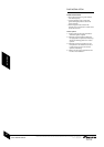
Any external device connected to the
boiler must take its power supply from
the boiler supply only and must NOT
have a separate supply.
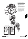
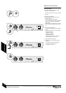
External 230V programmer
(terminal block X4):
4 Remove 4 pin plug (M) from X4.
Remove test links (P) from plug block (M).
Connect wires to plug block (M) as shown.
Fit plug into terminal block X4.
Connect earth to terminal block X1connector
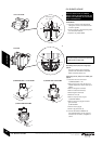
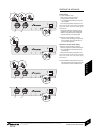
230V room thermostat (terminal block X2):
6 Remove link (K).
Connect LIVE supply to terminal L
S.
Connect SWITCHED LIVE supply to
terminal LR.
NOTE: This is sometimes refered to as ‘call
for heat’ or ‘heating load’.
Connect NEUTRAL to terminal Ns.
NOTE: Some devices do not require this.
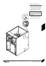
Refit electric control panel cover:
Refit panel (C) and secure with screws (B).
NOTE: Both frost thermostats are fitted as
standard to the external appliance to provide
frost protection.
C
B
A
4
P
M
G
D
E
2/3
230V
MAINS
SUPPLY
X2
6
Neutral (if required)
Switched Live
Live
FROST
STAT(1)
FROST
STAT(2)
7 k 7
ROOMSTAT
Accelerator
resistor
(if fitted)
PROGRAMMER (EXTERNAL)
5
clock
CH channel
HW channel
N Supply
L Supply
HW Demand
CH Demand
X4
Fuse
CONTROL
BOARD
.
M
B
G
F