


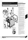
BOILER INSTALLATION
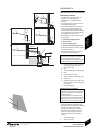
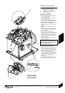
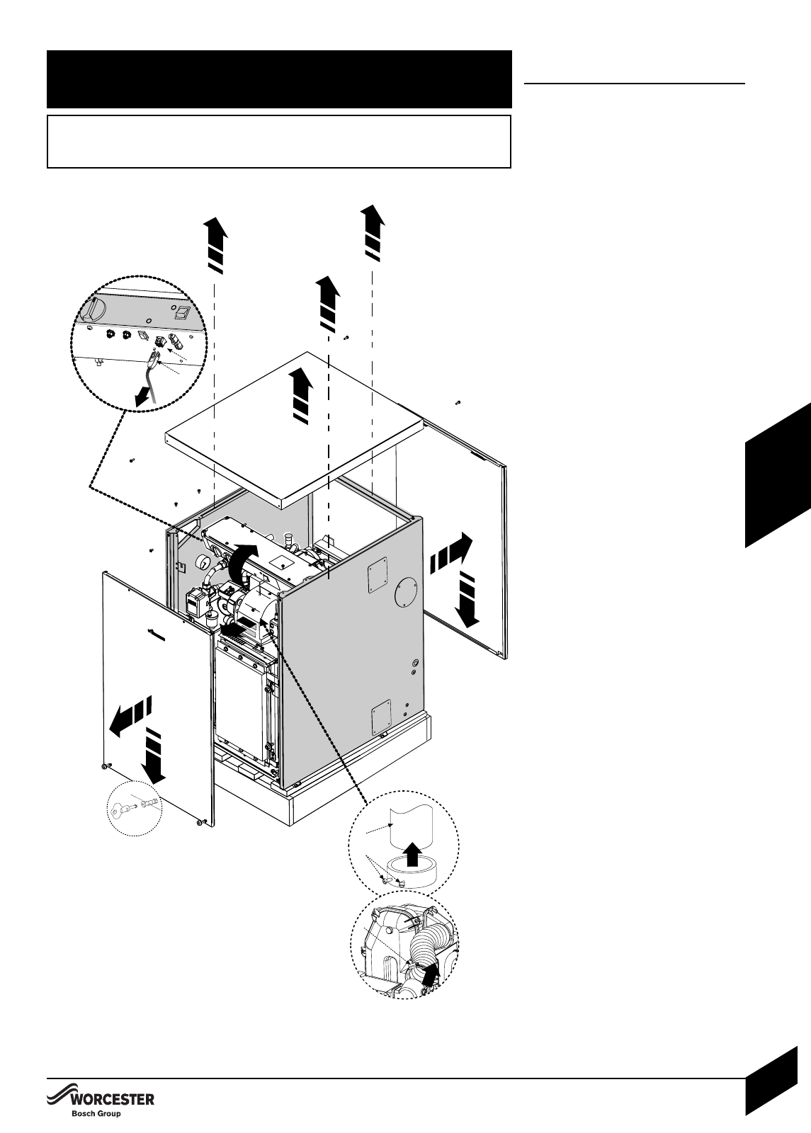
Note: The cabinet is not load bearing it
only provides weather protection for the
boiler inside.
1Mark position of the 100mm services
duct on the exterior wall and make a hole
through.
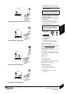
2Remove the key for the door fastners
from its transport position in the left hand
side panel flue outlet aperture.
Undo the screws at the bottom of
the front panel (using the key provided)
and remove the screws from the rear
panel pulling both panels out and down
to remove. Store safely away from the
installation point.
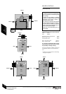
3Remove the screws from the top panel
and lift up to remove, store safely away
from the installation point.
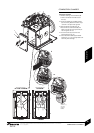
4Slide the pressure gauge up out of its
bracket and carefully rest on top of the
heat exchanger taking care not to snag or
kink the capillary.
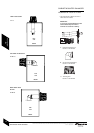
5Remove the screws securing the control
box to the side panels and carefully rest
the control box on top of the heat
exchanger taking care not to snag or kink
the capillaries.
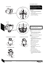
6Remove the screws securing the side
panels to the base panel and lift the side
panels off complete with the rear support
bar (shaded grey) and carefully stand the
panels away from the installation point.
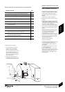
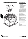
7Loosen the flexable air duct clamp (A)
and remove the air duct from the burner.
Depress the locking ears to unplug the
burner lead (B) from the control box (C).
Unscrew the burner retainers (D), then
withdraw the burner (E) from the boiler and
store safely away from the installation point.
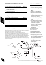
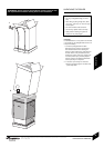
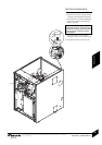
8Remove the screws securing the base
panel to the transit pallet and lift the boiler
off the pallet and into its installation
position taking care not to scrape the
base panel across the hard standing. Do
not attempt to lift and position the
boiler on your own. Do not use the
copper pipes to move the boiler.
Fasten the base to the hard standing
using the holes provided. Care should be
taken to ensure that the base is level.
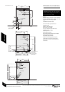
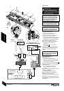
9Refit the side panels and rear support
bar and screw the side panels to the
baseplate and boiler.
Refit the control box and pressure
gauge taking care not to kink the
capillary tubes.
Measure the 100mmØ services duct to
give at least 10mm inside the casing and
to finish flush with the interior wall
surface, cut to size and fit the duct. Fit the
100mm sealing ring where the duct
enters the casing and seal the joint to the
exterior wall and inside the cabinet with a
suitable sealant.
BOILER INSTALLATION
INSTALLATION & SERVICING INSTRUCTIONS FOR WORCESTER GREENSTAR HEATSLAVE EXTERNAL 12/18-18/25-25/32
8 716 113 389b (09/07)
20
INSTALLATION
2
2
3
45
6
7
8
7
A
B
C
D
E
WARNING: THIS APPLIANCE IS SERVICED AND REPAIRED EXTERNALLY.
EXTERNAL EQUIPMENT OPERATED AT 230V SHOULD NOT BE INSTALLED, SERVICED OR
REPAIRED UNDER ADVERSE WEATHER CONDITIONS.
THIS APPLIANCE IS INSTALLED AND SERVICED EXTERNALLY TO THE PROPERTY, BUT
THE ENGINEER MUST HAVE ACCESS TO THE INSIDE OF THE PROPERTY WHEN
INSTALLING OR SERVICING THE APPLIANCE.