


PIPEWORK CONNECTIONS
INSTALLATION & SERVICING INSTRUCTIONS FOR WORCESTER GREENSTAR HEATSLAVE EXTERNAL 12/18-18/25-25/32
8 716 113 389b (09/07)
23
INSTALLATION
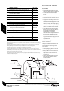
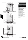
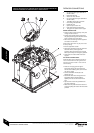
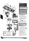
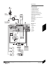
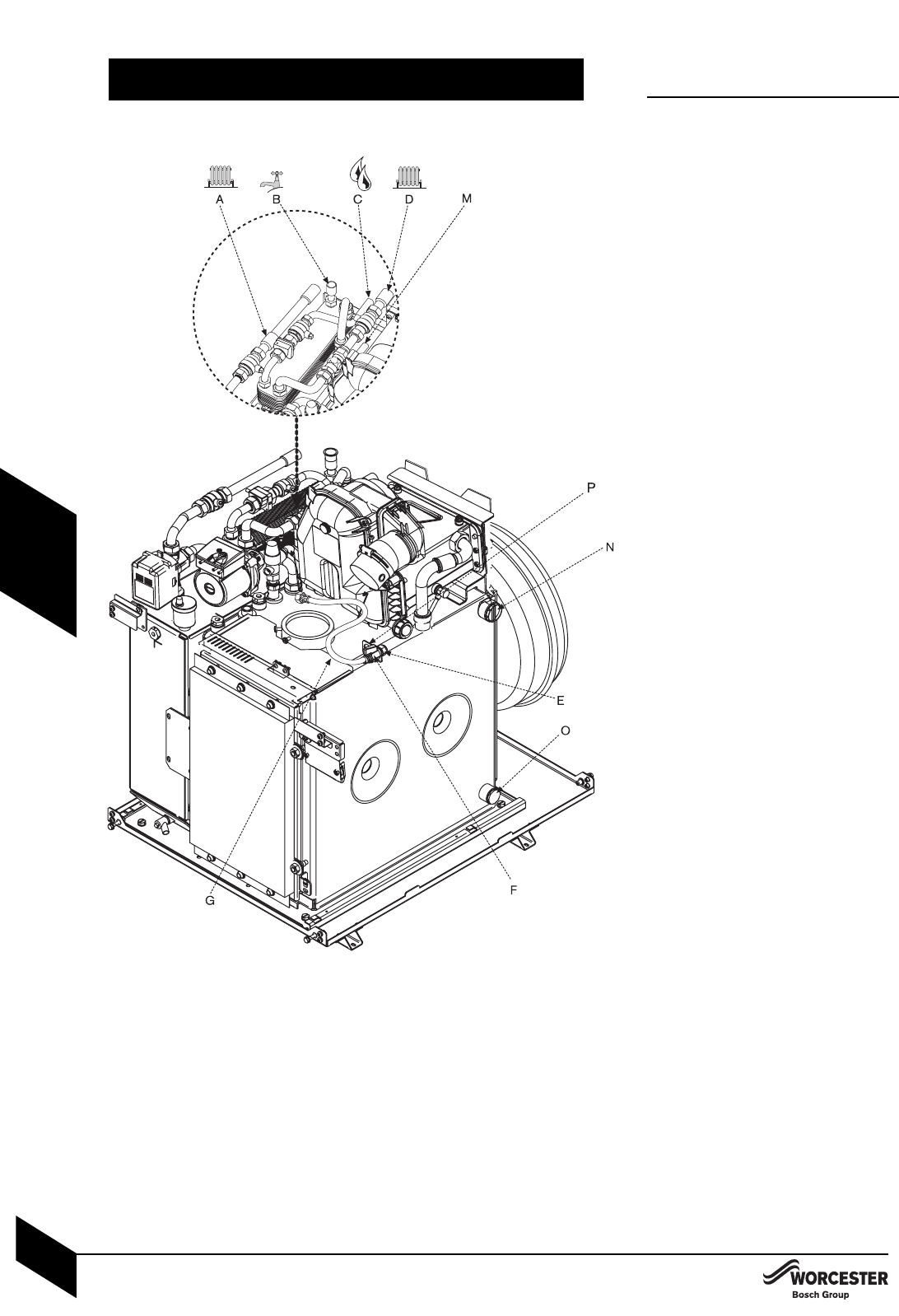
PIPEWORK CONNECTIONS
A - CH flow 22mmØ copper (28mmØ on
25/32 models)
B - DHW flow 22mmØ
C - Water main inlet 15mmØ
D - CH return 22mmØ copper (28mmØ on
25/32 models)
E - 10mmØ oil supply pipe connection
F - Oil isolating valve (10mmØ)
G - Flexible oil hose
N - Optional open vent/air vent
O - Drain/optional feed and expansion
P - Fixing point for optional return oil pipe
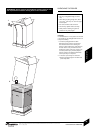
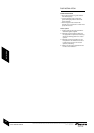
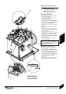
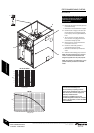
WATER CONNECTIONS:
All service pipes into the property must pass
through the services duct.
Insulate all the system/supply pipes where
the pipes pass through the duct with at least
22mm insulation around the pipes.
Remove the transit bungs from the pipework
connections on the boiler.
NOTE: that surplus water may be present due
to factory testing.
Ensure all pipework is clean.
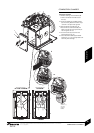
Align water pipework through the 100mm Ø
duct and connect, ensuring that the
expansion tank and control box fit correctly
before permanently connecting the pipework.
Check that all unused sockets have been
capped.
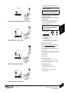
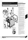
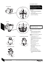
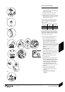
OIL SUPPLY CONNECTIONS:
NOTE: Oil filters and de-aeration devices are
not to be fitted within the casing and the fire
valve body must be at least 1 metre from the
external casing.
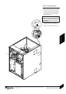
Route the oil supply pipe through the
appropriate casing hole as required and
connect to the isolating valve (F) and ensure
the valve is closed.
Connect the flexible oil hose (G) to the
isolating valve (F).
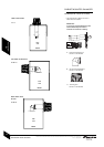
Pass the fire valve sensor through the most
appropriate casing hole and locate the
capillary in the cut out at the bottom of the
hole.
Clip the sensor into the clip provided at the
rear of the control box.
Rotate the cover plate and seal so it does not
cover the capillary, then secure with the screws
provided.
CAUTION: ISOLATE THE OIL & WATER MAINS SUPPLY BEFORE STARTING ANY
WORK AND OBSERVE ALL RELEVANT SAFETY PRECAUTIONS.