


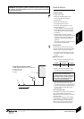
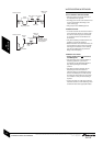
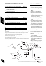
TYPICAL OPEN VENT SYSTEM
D
R R
R R
C
T
L
T
L
T
L
L
L
E
S
1000mm min.
F
G
D
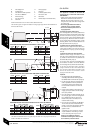
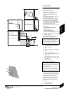
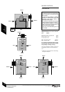
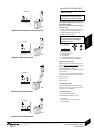
TYPICAL SEALED SYSTEM
D
R R
R R
B
P
D
C
T
L
T
L
T
L
L
L
A
U
H
G
INSTALLATIONCOMMISSIONING
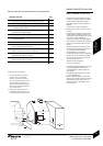
A - Appliance expansion vessel
B - Extra expansion vessel
C - Automatic bypass valve
D - Drain cock
E - Feed & expansion cistern
WATER SYSTEMS & PIPEWORK
INSTALLATION & SERVICING INSTRUCTIONS FOR WORCESTER GREENSTAR HEATSLAVE EXTERNAL 12/18-18/25-25/32
8 716 113 389b (09/07)
10
PRE -
INSTALLATION
F - Feed & expansion 15mmØ min
G - Appliance
H - Open vent 22mmØ min
L - Lockshield valve
P - Pressure relief discharge
R - Radiators
S - Static head
T - TRV
U - To filling system
WATER SYSTEMS & PIPEWORK
PRIMARY SYSTEM PLASTIC PIPEWORK:
• Plastic pipework must not
be used for
the DHW system.
• Any plastic pipework used for the CH system
must have a polymeric barrier, comply with
BS 7921 and installed to BS 5955 with
1000mm (minimum) length of copper or steel
pipe connected to the boiler.
• Plastic pipework used for underfloor heating
must be correctly controlled with a
thermostatic blending valve limiting the
temperature of the circuits to approx. 50°C
with 1000mm (minimum) length of copper or
steel pipe connected to the boiler.
PRIMARY SYSTEM/CONNECTIONS/VALVES:
• Do not use galvanised pipes or radiators.
• All system connections, taps and mixing
valves must be capable of sustaining a
pressure of 3 bar.
• Radiator valves should conform to
BS 2767:10.
• All other valves should conform to BS 1010.
• On new installations TRVs must be used on
all radiators except the radiator where the
room thermostat is sited, this must be fitted
with lockshield valves and left open. All
installations should have TRVs fitted to
radiators within the sleeping accommodation.
• An automatic bypass valve must be connected
between the heating flow and return where
TRVs are used on all radiators, fitted to give
at least a 3m circuit when activated.
• Drain cocks are required at all the lowest
points on the system.
• Air vents are required at all high points on the
system.
OPEN VENT PRIMARY SYSTEM:
• In order to comply with BS 5449 the feed
and expansion pipe and the open vent pipe,
(or the combined feed and vent pipe), must
be connected to the BSP outlet/s on the
right hand side of the primary heat exchanger.
• The feed and expansion cistern (E) must be
positioned to provide a static head (S) of at
least 1 metre above the highest point in the
heating system to the water level in the feed
and expansion cistern (E).
• Ensure adequate space is left in the expansion
cistern for expansion of the system water.
• No valve shall be fitted in the open vent pipe
(H) or the feed and expansion pipe (F).
• The open vent pipe (H) must be at least 22mmØ.
SEALED PRIMARY SYSTEM:
• Where the system volume is more than 180
litres at 0.5 bar or exceeds 2.65bar at
maximum heating temperature an extra
expansion vessel (B) must be fitted as close
as possible to the appliance in the central
heating return.
• Pressurise the extra expansion vessel (B) to
the same figure as the expansion vessel built
into the appliance.
IMPORTANT: The boiler should not be
allowed to operate with a return
temperature of less than 40°C when the
system is up to operating temperature.