


Instruction Manual – Model CF2500/CF3500 Oil Burner
9
Form 6104 BCF-35-R0699
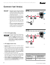
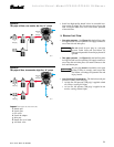
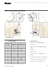
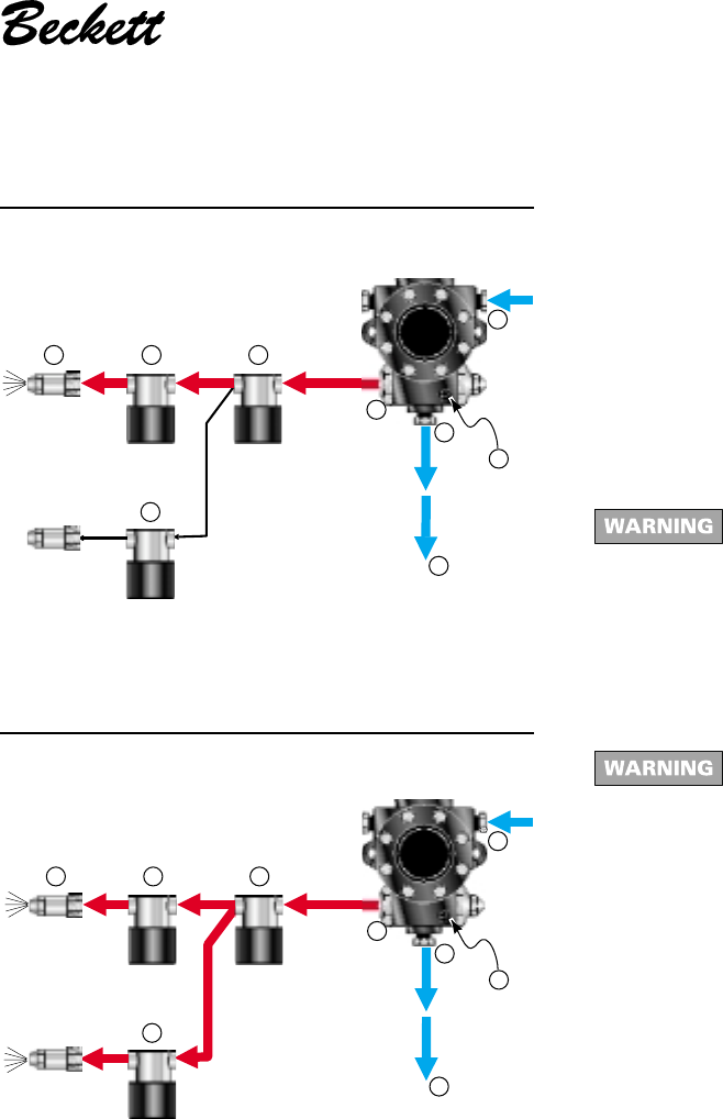
Figure 9a
Two-pipe oil flow, one nozzle, low fire, “H” pump
• Install two high-quality shutoff valves in accessible loca-
tions on the oil supply line. Locate one valve close to the
tank. Locate the other valve close to the burner, upstream
of the fuel filter.
❏ Burner fuel flow
• One-pipe systems – See Figure 8 for the fuel flow paths
for high-fire and low-fire operation. Oil supply connects to
one of the fuel unit Inlet ports.
Do not install by-pass plug in a one-pipe
system. Could cause unit seal failure, oil
leakage and potential fire and injury hazard if
ignored.
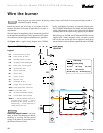
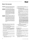
• Two-pipe systems – See Figure 9 for the fuel flow paths
for high-fire and low-fire operation. Oil supply connects to
one of the fuel unit Inlet ports. Oil return connects to the
fuel unit Return port.
By-pass plug must be installed in a two-pipe
system. Failure to comply could cause unit
seal failure, oil leakage and potential fire and
injury hazard.
• Low-fire/high-fire operation – The fuel unit nozzle port
pressure is factory set at 300 psig.
• At high fire, full pressure (300 psig) is applied at both
oil nozzles, causing full input.
• At low fire, full pressure (300 psig) is applied at one
nozzle, causing reduced input.
Figure 9b
Two-pipe oil flow, two nozzles, high fire, “H” pump
a Return port
b Nozzle port
c Oil valves
d Nozzle & adapter
g Inlet port
k Return line to oil tank
p Air bleed valve
Legend (for Figures 8a, 8b, 9a and 9b)
3512
d
200 psig
to
300 psig
cc
c
k
200 psig
to
300 psig
b
g
a
p
3513
d
200 psig
to
300 psig
cc
c
k
200 psig
to
300 psig
200 psig
to
300 psig
b
g
a
p