


Instruction Manual – Model CF2500/CF3500 Oil Burner
4
Form 6104 BCF-35-R0699
Pre-installation checklist
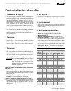
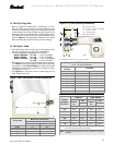
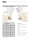
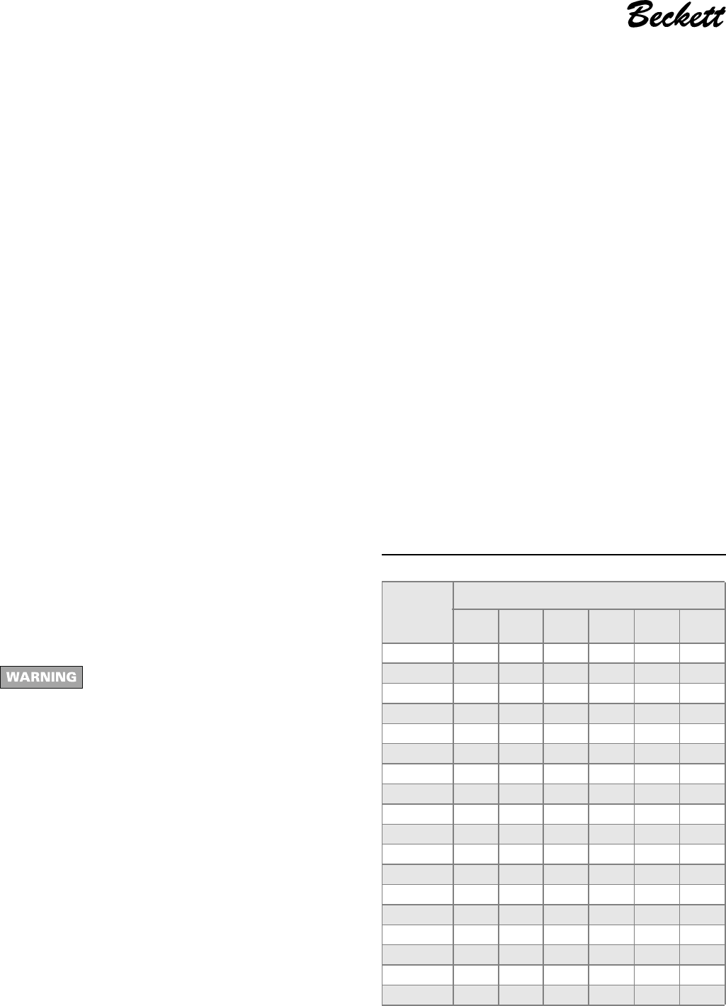
Table 1 – Nozzle capacities at various pressures
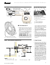
❏ Combustion air supply
• The burner requires combustion air and ventilation air for
reliable operation. Assure that the building and/or com-
bustion air openings comply with National Fire Protection
Standard for Oil-Burning Equipment, NFPA 31. For appli-
ance/burner units in confined spaces, the room must have
an air opening near the top of the room plus one near the
floor, each with a free area at least one square inch per
1,000 Btu/hr input of all fuel burning equipment in the
room. For other conditions, refer to NFPA 31 (CSA B1139-
M91 in Canada).
• If there is a risk of the space being under negative pressure
or of exhaust fans or other devices depleting available air
for combustion and ventilation, the appliance/burner
should be installed in an isolated room provided with out-
side combustion air.
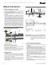
❏ Clearances
• With the burner installed in the appliance, there must be
adequate space in front of and on the sides of the burner to
allow access and operation. Verify that the clearance di-
mensions comply with all local codes and with the appli-
ance manufacturer's recommendations.
❏ Fuel supply
• The fuel supply piping and tank must provide #1 or #2
fuel oil at pressure or vacuum conditions suitable for the
fuel unit (oil pump) on the burner. Refer to fuel unit litera-
ture in the literature envelope in the burner carton to verify
allowable suction pressure.
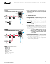
The fuel unit is shipped without the by-pass
plug installed. You must install this plug on
two-pipe system. DO NOT install the by-pass
plug in the fuel unit if connected to a one-
pipe oil system. Failure to comply could cause
fuel unit seal failure, oil leakage and potential
fire and injury hazard.
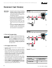
When fuel supply is level with or higher than burner
fuel unit —
• When the fuel unit is not required to lift the oil, the instal-
lation is usually suitable for either a one-pipe or two-pipe
oil system. The oil pressure at the inlet of the fuel unit must
not exceed 3 psig.
• See Figure 8 for one-pipe fuel supply installations. See
Figure 9 for two-pipe fuel supply installations.
When fuel supply is below the burner fuel unit —
• Use a two-pipe oil system when the fuel unit must lift the
oil more than 2 feet. The return line provided by the two-
pipe system is needed to purge the air from the fuel lines
and minimize the likelihood of air-related problems dur-
ing operation.
❏ Vent system
• The flue gas venting system must be in good condition
and must comply with all applicable codes.
❏ Electrical supply
• Verify that the power connections available are correct for
the burner. All power must be supplied through fused dis-
connect switches.
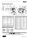
❏ Verify burner components —
• Burner box, Model CF2500A/CF2500/CF3500A
• Air tube assembly (selected per following)
• Mounting flange kit
• Pedestal mounting assembly kit (recommended)
• Oil nozzle, per Table 1 — Use only 45° to 70° solid pat-
tern nozzles unless otherwise shown by appliance manu-
facturer.
The CF2500A, CF2500 and CF3500A are dual nozzle burn-
ers. To select the nozzles, use half of the maximum firing
rate and select a nozzle under the 300 psig column (high
fire rate). Select the corresponding nozzle from column 1
(Rated gph @ 100 psig). Two nozzles will be required.
Rated
gph @
100 psig
Pressure - pounds per square inch
125 150 175 200 250 300
5.00 5.59 6.13 6.61 7.07 7.50 8.66
5.50 6.15 6.74 7.27 7.78 8.70 9.54
6.00 6.71 7.33 7.94 8.48 9.49 10.40
6.50 7.26 7.96 8.60 9.20 10.30 11.25
7.00 7.82 8.56 9.25 9.90 11.06 12.12
7.50 8.38 9.19 9.91 10.60 11.85 13.00
8.00 8.94 9.80 10.58 11.31 12.65 13.85
8.50 9.50 10.45 11.27 12.06 13.40 14.70
9.00 10.06 11.02 11.91 12.73 14.20 15.60
9.50 10.60 11.70 12.60 13.50 15.00 16.45
10.00 11.18 12.25 13.23 14.14 15.81 17.32
10.50 11.74 12.85 13.90 14.85 16.60 18.18
11.00 12.30 13.47 14.56 15.55 17.39 19.05
11.50 12.85 14.08 15.22 16.26 18.18 19.92
12.00 13.42 14.70 15.87 16.97 18.97 20.78
12.50 13.98 15.31 16.54 17.68 19.76 21.65
13.00 14.54 15.92 17.20 18.38 20.55 22.52
13.50 15.10 16.53 17.85 19.09 21.34 23.38