


Instruction Manual – Model CF2500/CF3500 Oil Burner
15
Form 6104 BCF-35-R0699
Maintenance and service
Annual service
— by qualified service technician
Have the burner inspected, tested and started at least annually
by a qualified service technician. This annual test/inspection
should include at least the following:
❏ Replace oil nozzles.
❏ Clean burner and blower wheel (if needed to remove lint
or debris).
❏ Test ignition and combustion at low and high fire and
verify air damper settings.
❏ Test oil supply line vacuum - verify that it is within al-
lowable range indicated in fuel unit literature.
❏ Check pump pressure to nozzles at low and high fire.
❏ Inspect fuel system (including tank, lines and all connec-
tions).
❏ Inspect combustion air and vent systems.
❏ Replace oil filter.
❏ Oil motor (if not permanently lubricated).
Monthly maintenance
— by owner
❏ Observe combustion air openings and vent system for
integrity. Openings must be clean and free of any obstruc-
tions.
❏ Check the oil lines and fittings to verify there are no leaks.
❏ Observe burner ignition and performance to verify smooth
operation.
❏ Shut the system down if you observe abnormal or ques-
tionable operation. Call a qualified service agency for
professional inspection and service.
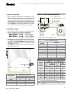
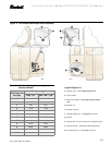
b. Slowly rotate the air adjusting plate (increase the
amount of air) as the damper drives to high-fire.
c. Lock down air adjusting plate at the high-fire air set-
ting found in Table 5 for the high-fire rate.
6. Use combustion test instruments to adjust the burner.
a. Adjust the air until a trace of smoke is achieved with
CO
2
level as high as possible (lowest possible O
2
).
Example: 13.5% CO
2
(2.5% O
2
) with a trace of smoke.
b. Increase the air to reduce CO
2
by 2 percentage points
at a zero smoke level. (Increase O
2
by 3 percentage
points at a zero smoke level.)
Example: Reduce CO
2
from 13.5% to 11.5%, with zero
smoke (or increase O
2
from 2.5% to 5.5%).
c. A margin of reserve air has been added to accommo-
date variable conditions.
7. Check the breech draft pressure against the appliance
manufacturer’s recommended setting (typically + 0.1"
W.C.).
8. If the breech pressure is higher or lower than recommended
level, adjust the appliance breech damper to achieve the
specified setting. Recheck the smoke and CO
2
levels.
Adjust burner air if necessary.
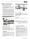
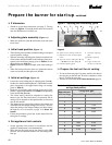
9. Once all settings are complete and satisfactory, rotate the
damper linkage arm (Figure 12, item f) until it touches
the damper rod (Figure 12, item d) and tighten the damper
linkage arm screw securely.
❏ Set low-fire air
1. Loosen the air adjusting plate (Figure 12, item m) screw
and set the air adjusting plate at the low-fire air setting
found in
Table 5, page 13. The damper should stay at the
high-fire setting. The damper linkage will prevent move-
ment of the damper plate.
2. Move the low-fire hold switch from the “
OUT” to the
“IN” position.
a. The damper will return to the low-fire air setting.
3. Check the smoke and CO
2
(O
2
) levels.
a. Pull a smoke sample from the flue.
b. The sample should be clean (zero smoke level).
c. Check the CO
2
(O
2
) level:
CO
2
should be at 11 to 12% (O
2
at 5.9 to 4.5%).
If the CO
2
is less than 11% (O
2
more than 5.9%), decrease
the air and check the smoke level.
4. Operate the burner from low fire to high fire and back to
verify operation.
5. Turn the burner off. Wait one or two minutes (for chamber
to clear) and then turn on again to verify starting charac-
teristics.
6. Perform limit circuit performance test specified by appli-
ance manufacturer to verify operation of burner/appli-
ance combination.
The burner must be serviced at least annually by a qualified service technician to assure continued reliable
operation. Operation and adjustment of the burner requires technical knowledge and the use of combustion test
instruments. Do not tamper with the burner or controls. Failure to comply could result in failure of the burner or
system, resulting in severe personal injury, death or substantial property damage.