


Instruction Manual – Model CF2500/CF3500 Oil Burner
13
Form 6104 BCF-35-R0699
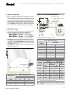
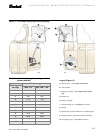
Table 5 – Initial air adjusting plate settings
(damper position)
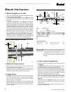
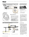
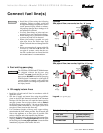
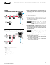
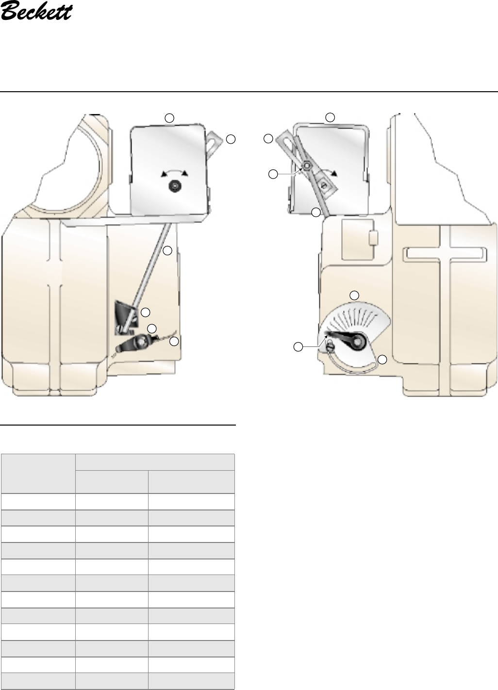
Figure 12 – Air damper and damper motor assembly
Legend (Figure 12)
a Damper motor – do not adjust internal cam
b Arm assembly
c Ball joint assembly – do not adjust position of ball
joint
d Damper rod
e Damper rod guide
f Damper linkage arm - sets high-fire air position
g Damper
h Damper label - position indicator for air adjusting plate
k Damper indicator - permanently attached to damper
m Air adjusting plate - sets low-fire air position
Approximate
adjusting plate
settings
Firing rate, gph
Tube “KP” Tube “KM”/“KR”
0 -- --
1 8.00 8.00
2
9.00 9.00
3 11.00 11.00
4 12.00 12.00
5
15.00 15.00
6 17.00 17.00
7 18.00 19.00
8
19.00 22.00
9 20.00 25.00
10 22.00 29.00
10.5
25.00 35.00
CLOSE OPEN
3516
a
b
d
e
f
g
3517
CLOSE
a
b
d
c
12
0
1
2
3
4
5
6
7
8
9
10
1
1
h
k
m