


Instruction Manual – Model CF2500/CF3500 Oil Burner
6
Form 6104 BCF-35-R0699
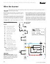
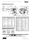
Mount the burner
❏ Mount flange(s) on air tube
• This section does not apply to burners with welded flanges.
• Do not install air tube on burner.
• For non-pressure firing flange, refer to
Figure 3: Install
gasket (item
a) and flange (item d). Ignore the next
paragraph.
• For pressure-firing flange, refer to
Figure 3: Slide gasket
(item
a) onto the air tube, making sure the top of the air
tube is up. Predrill holes in the pressure firing plate (item b)
to match the appliance studs. Slide the pressure firing plate
(item b) and flange (item d) onto the air tube as shown.
Wrap ceramic fiber rope (item c) around the air tube and
press tightly into the inside diameter of the flange (item
d).
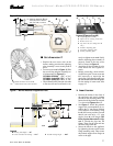
• Slide the air tube (item
e) into position in the appliance
front. Tighten the flange-mounting-stud nuts. Set the
insertion of the air tube so dimension G is ¹⁄₄" nominal.
• Pitch the air tube at 2° from horizontal as shown and secure
the flange to the air tube. Remove the flange-mounting
stud nuts and remove the air tube from the appliance.
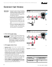
❏ Install nozzle line assembly
• Insert the nozzle line assembly into the burner air tube as
in Figure 5.
• See Figures 5 and 6. Assemble the adjusting plate assem-
bly per the instructions in the assembly packet.
• Slide the secondary adjusting plate (item f) completely to
the left on the indicator adjusting plate (item e). Finger-
tighten acorn nut c to secure the two plates together. Slide
both plates completely to the left on the primary adjusting
plate (item g) and finger-tighten acorn nut d.
• Slide the completed adjusting plate assembly over the
nozzle line end. Move the plate assembly and the nozzle
line so the plate assembly fits into position as shown in
Figure 5.
• Install the spline nut (Figure 5, item b) on the end of the
nozzle line, leaving the nut loosely placed so the plates
can be moved.
• Connect the high-voltage leads from the ignition trans-
former to the electrodes.
❏ Mount air tube to burner
• Remove the rear access door from the back of the burner
for improved access to the interior.
• Attach the air tube to the burner with the bolts and acorn
nuts provided. The acorn nuts must go on the outside of
the burner, with the bolts inserted from the inside.
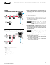
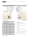
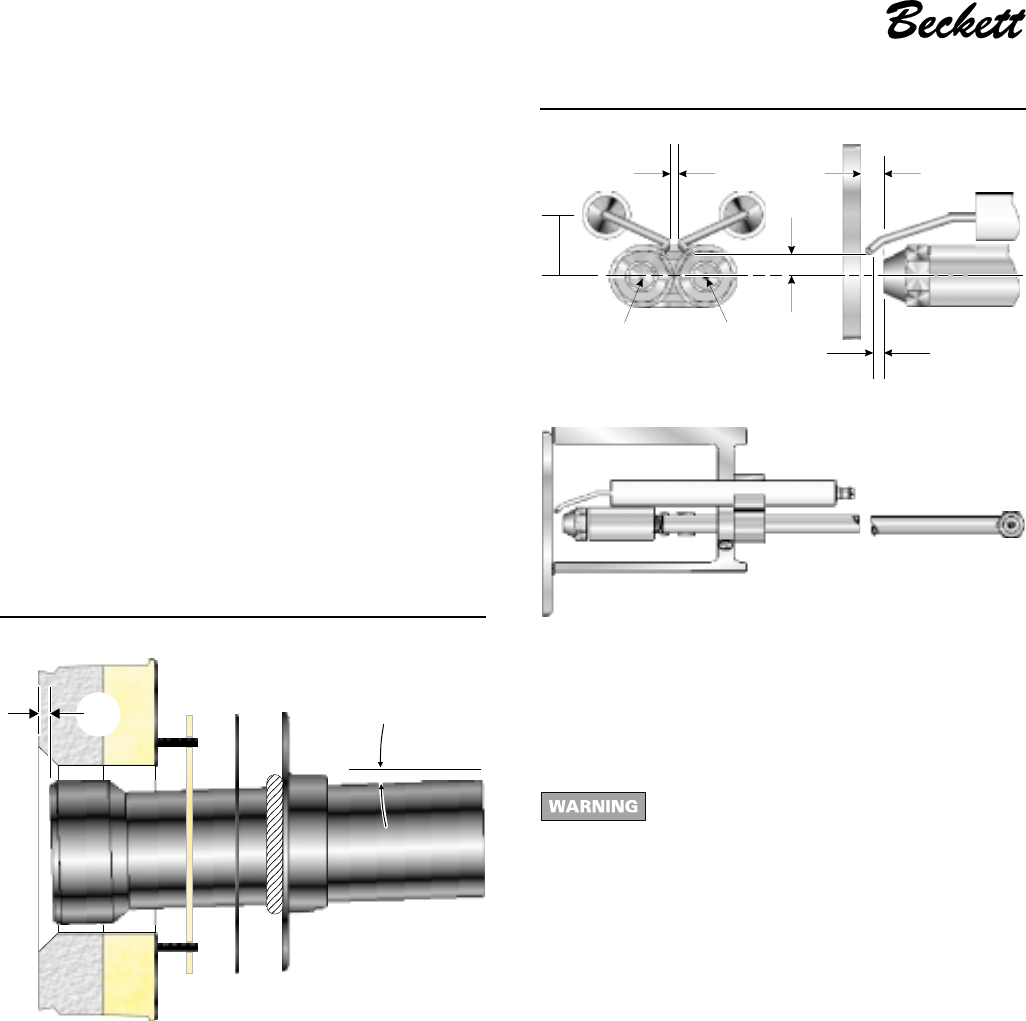
❏ Install nozzle
• See Figure 4. Install the oil nozzle in the nozzle adapter.
Use a ³⁄₄" open-end wrench to steady the nozzle adapter
and a ⁵⁄₈" open-end wrench to turn the nozzle. Tighten
securely but do not overtighten.
• Check, and adjust if necessary, the critical dimensions P,
Q, R and S shown in the drawing. Verify that the oil tube
assembly and electrodes are in good condition, with no
cracks or damage.
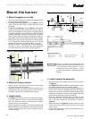
Figure 4 – Nozzle and nozzle line assembly
Figure 3 – Mount flange(s) on air tube
Failure to properly set and maintain the
electrode and nozzle spacing dimensions can
cause incorrect burner ignition or poor
combustion. This could result in severe
personal injury, death or substantial property
damage.
Critical dimensions —
S
(Electrode spacing)
= ³⁄₃₂"
Q
(Nozzle to head)
= ¹⁄₄"
P
(Nozzle center line to electrode tip)
= ¹⁄₄"
R
(Nozzle face to electrode tip)
= ¹⁄₈"
3504
P
R
QS
0.713311"
Low fire
nozzle
High fire
nozzle
3505
3503
2°
G
abd
c
e