


Instruction Manual – Model CF2500/CF3500 Oil Burner
12
Form 6104 BCF-35-R0699
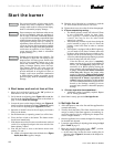
Prepare the burner for start-up - continued
❏ Z dimension
• Should be set per these instructions (see page 7). The top
acorn nut (Figure 11, item d) should never be loosened
once the Z dimension is initially set.
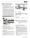
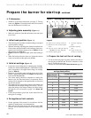
❏ Adjusting plate assembly (Figure 11)
• Make sure spline nut (item b) and bottom acorn nut (item
c) are loose.
❏ Initial head position (Figure 11)
• The indicator plate assembly (item e) markings correspond
to head position settings.
• Slide the secondary adjusting plate (item f) toward the rear
of the burner until the number on the indicator plate corre-
sponds to the initial head setting given in Table 4 for the
desired firing rate (high-fire).
• Figure 11 shows a typical example, with a head setting of
5.
• When the head position has been set, tighten the bottom
acorn nut (item c) and the spline nut (item b).
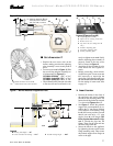
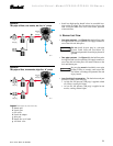
❏ Initial air settings (Figure 12)
• Loosen the screw holding the air adjusting plate (item m).
Set the air to the desired low-fire rate. (The numbers on this
plate correspond to the approximate firing rate settings
given in Table 5.)
• Rotate the air adjusting plate until the lower edge of the
pointer is opposite the number from Table 5 corresponding
to the desired low-fire rate.
• This initial setting should be adequate for starting the
burner at low fire. Once the burner is in operation, the air
setting will be adjusted for best performance as discussed
later in this manual.
• The damper moves to high-fire position as the damper rod
(item d) rotates the damper linkage arm (item f). You will
adjust the setting of the damper linkage arm when setting
the high-fire air as discussed on page 14 in Start the
burner
.
• Follow the procedures given later in this manual for fine
tuning the air settings.
❏ Set appliance limit controls
• Set the appliance limit controls in accordance with the
appliance manufacturer's recommendations.
• Move the low-fire hold switch (not shown) to the “IN”
position. This will hold the burner in low fire during initial
start-up.
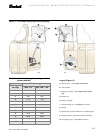
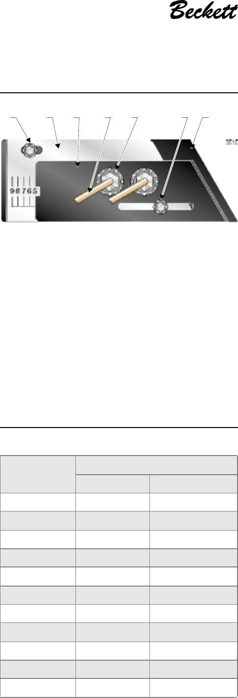
Legend
b Spline nut for securing nozzle line
c Bottom acorn nut (for head adjust-
ments
d Top acorn nut (for setting dim. Z only
— do not loosen after setting Z)
e Indicator adjusting plate
Figure 11 – Adjusting plate initial setting, typical
f Secondary adjusting
plate
g Primary adjusting
plate
h Copper oil line from
oil valve to nozzle line
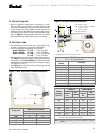
Table 4 – Initial indicator adjustment plate
settings (head position)
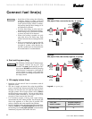
❏ Prepare the fuel unit for air venting
• To vent air from one-pipe oil systems, attach a clear hose to
the vent plug on the fuel unit. Provide a container to catch
the oil. Loosen the vent plug.
• Vent the air as described under Start the burner, page 14.
3515
e
g
df
b
h
c
Approximate
head settings
Firing rate, gph
Tube “KP” Tube “KM”/“KR”
0 -- --
1
-- 17.00
2 -- 17.50
3 17.00 18.00
4
17.50 18.50
5 18.00 19.00
6 18.50 20.00
7
19.00 21.00
8 20.00 28.00
9 21.00 32.00
10
25.00 35.00