


Instruction Manual – Model CF2500/CF3500 Oil Burner
14
Form 6104 BCF-35-R0699
Start the burner
Do not proceed unless all prior steps in this
manual have been completed. Failure to
comply could result in severe personal injury,
death or substantial property damage.
Do not attempt to start the burner when excess
oil has accumulated, when the appliance is
full of vapor or when the combustion chamber
is very hot. Do not attempt to reestablish flame
with the burner running if the flame should be
extinguished during start-up, venting or
adjustment. Allow the unit to cool off and all
vapors to dissipate before attempting another
start. Failure to comply with these guidelines
could cause an explosion or fire, resulting in
severe personal injury, death or substantial
property damage.
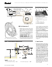
Damper motor and motor arm assembly - Do
not attempt to adjust the cam setting in the
damper motor. It is factory preset. Do not move
the ball joint assembly further out on the
motor arm assembly. This would change the
timing of damper opening versus fuel rate.
The damper linkage arm screw must be
tightened securely to assure the damper will
provide sufficient air at high fire. Failure to
comply could cause unreliable combustion
or flame failures, leading to possible severe
personal injury, death or substantial property
damage.
❏ Start burner and vent air from oil line
1. Move the low-fire hold switch to the “IN” position (to
hold burner in low fire when started).
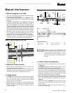
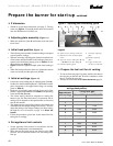
2. Verify that the air adjusting plate (Figure 12, item m) has
been set to the initial low-fire air position as described on
page 12 under Initial air settings.
3. Loosen the screw on the damper linkage arm (Figure 12,
item f) and allow the damper indicator (Figure 12, item k)
to rest on the air adjusting plate (Figure 12, item m).
4. Open the oil shutoff valves in the oil supply (and return)
line(s) to the burner.
5. Set the thermostat (or operating control) to call for heat.
6. Close the line switch to the burner. The burner motor
should start immediately.
7. If the burner motor does not start, reset the motor overload
switch (if so equipped) and press the reset switch of the
burner primary control.
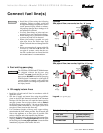
8. Vent the fuel unit as soon as the burner motor starts
rotating. To vent —
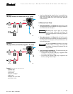
❏ Attach a clear plastic tube to the air bleed valve (Figure
8a, 8b, 9a or 9b
as applies, item p).
❏ Place the end of the tube in a container to catch the
oil. Then loosen the fuel unit air vent valve.
❏ Tighten the air vent valve after all air has been purged.
❏ IF burner stops during venting —
• The burner primary control will lockout if flame
is not established within its time limit.
This is typically 15 seconds for R8184 primary
controls, but may be less for other flame
supervisory controls.
• The burner may lockout several times during the
period needed to purge all the air. Reset the
primary control each time in order to continue
purging.
• If the burner is equipped with an R8184 primary,
you will need to wait about 2 minutes after each
lockout to allow time for the reset switch to cool.
• Squeeze off the air bleed tubing or close the air
vent valve when the pump stops running to prevent
air from flowing back into the oil line.
If the fuel unit air vent valve is completely
open, assuring no flow of oil to the burner oil
nozzle, you can temporarily jumper the F-F
terminals of an R8184 primary during the
purge period to allow enough time for all air
to purge. Never leave the burner unattended
when doing this. Remove the jumper when
purging is completed. This procedure should
only be used by a qualified burner technician,
experienced in burner operation and
control. Improper application of this method
can cause combustion chamber explosion, fire
hazard or fuel leakage, resulting in severe
personal injury, death or substantial property
damage.
❏ IF burner stops after flame established —
• Additional venting is probably required. Repeat
the air venting procedure.
9. Once flame is steady, proceed to Set high-fire air.
❏ Set high-fire air
1. Allow the burner to run at low fire until the appliance has
warmed sufficiently.
2. Visually check the flame. The flame should not be dark
orange or smoky. If the flame appears to be smoking, in-
crease the amount of air by readjusting the damper indi-
cator to a higher number.
3. Once the appliance has warmed, the high-fire setting can
be checked and adjusted.
4. Locate the approximate air adjusting plate setting for high
fire in Table 5, page 13.
5. Place the low-fire hold switch in the “OUT” position.
The damper motor will begin to rotate.
a. At the same time, loosen the screw securing the air
adjusting plate (Figure 12, item m) as the damper be-
gins to move.