


Instruction Manual – Model CF2500/CF3500 Oil Burner
8
Form 6104 BCF-35-R0699
Connect fuel line(s)
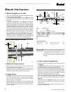
❏ Fuel unit by-pass plug
The CF2500A, CF2500 and CF3500A burners
are shipped without the by-pass plug
installed. You must install this plug on two-
pipe systems. DO NOT install the by-pass plug
in the fuel unit if connected to a one-pipe oil
system. Failure to comply could cause fuel
unit seal failure, oil leakage and potential fire
and injury hazard.
❏ Oil supply/return lines
• Install the oil tank and oil lines in accordance with all
applicable codes.
• Size the oil supply and return lines using the guidelines
given in the fuel unit literature included in the literature
envelope. Oil line flow rate will equal the burner rate for
one-pipe systems. For two-pipe systems, refer to Table 3
for the fuel unit gearset capacity - the rate at which fuel is
recirculated when connected to a two-pipe system. Size
two-pipe oil lines based on this flow rate.
• Use continuous lengths of heavy-wall copper tubing,
routed under the floor where possible. Do not attach fuel
lines to the appliance or to floor joists if possible. This
reduces vibration and noise transmission problems
• Install an oil filter sized to handle the fuel unit gearset flow
capacity (Table 3) for two-pipe systems. Size the filter
for the firing rate for one-pipe systems. Locate the filter
immediately adjacent to the burner fuel unit.
• Install the oil lines using the following
guidelines. Failure to comply could lead
to equipment damage and present a risk of
severe personal injury, death or substan-
tial property damage due to leakage of oil
and potential fire hazard.
• Use only flare fittings at joints and con-
nections. Never use compression fittings.
• Install fittings only in accessible locations
to assure any leak will be detected.
• Where joint sealing is needed, use only
pipe dope. Never use Teflon tape. Tape
strands can break free and damage the fuel
unit.
• Never use a one-pipe oil system with a lift
in excess of 2 feet with an H fuel unit. On
two-pipe oil systems, verify that the suc-
tion line vacuum does not exceed the fuel
unit manufacturer’s recommendation.
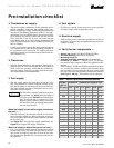
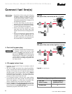
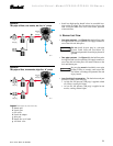
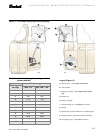
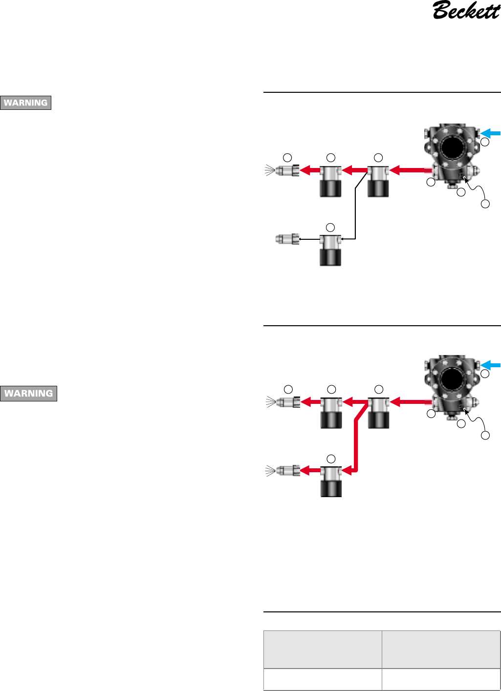
Figure 8a
One-pipe oil flow, one nozzle, low fire, “H” pump
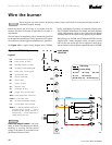
Legend (see opposite page)
Figure 8b
One-pipe oil flow, two nozzles, high fire, “H” pump
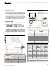
Table 3 - Fuel unit gearset capacities
3510
200 psig
to
300 psig
d
200 psig
to
300 psig
b
g
a
cc
p
c
3511
d
200 psig
to
300 psig
cc
c
200 psig
to
300 psig
200 psig
to
300 psig
b
g
a
p
Fuel unit
model number
Gearset capacity
(gallons per hour)
H5PAN-C100H 79