


Instruction Manual – Model CF2500/CF3500 Oil Burner
10
Form 6104 BCF-35-R0699
Wire the burner
Install the burner and all wiring in accordance with the
National Electrical Code and all applicable local codes or
requirements.
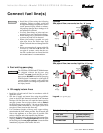
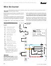
Wire the burner in compliance with all instructions provided
by the appliance manufacturer. Verify operation of all controls
in accordance with the appliance manufacturer's guidelines.
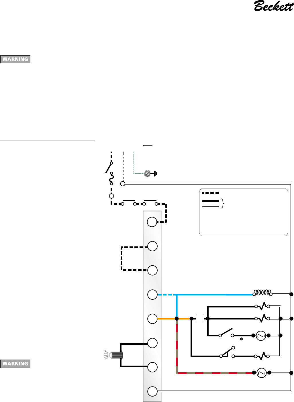
See
Figure 10 for a typical wiring diagram for a CF2500A
Do not by-pass any safety control. By-passing a safety control could result in severe personal injury, death or
substantial property damage.
burner, with R8184 oil primary, for reference purposes only.
The CF2500/CF3500A burner is available with many different
wiring configurations. Refer to the wiring diagram shipped
with the burner for the actual wiring applying to your burner.
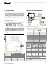
When firing over 20 GPH, the CF2500 and CF3500A will be
supplied with a flame safeguard control. An airflow switch
and low-fire start switch may also be supplied. Consult local,
state and federal codes for burner requirements above 20 GPH.
Legend
FD Fused disconnect, by others
LM Limit controls, by others
OP Operating controls, by others
PR Oil primary control, R8184 typical
CC Flame sensor, cad cell typical
TM Optional delay timer
TR Ignition transformer
M1 Burner motor
S1 Primary oil valve
S2 High-fire valve
S3 Redundant oil valve
DM Damper motor and end switch
∗∗
∗∗
∗ H/L Insert high/low-fire control here
LFHS Low-fire hold switch
T–T 24-volt thermostat/limit terminals
F-F Cad cell flame sensor terminals
Electrical shock hazard - can cause
injury or death. Disconnect power before
installing or servicing. Provide ground
wiring to the burner in accordance with
the National Electrical Code.
Figure 10 – CF2500A Typical wiring
Note 1 — Indicates alternate wiring for in-
terrupted ignition controls — connect
transformer to blue primary lead. For in-
termittent duty — connect transformer to
orange primary lead only.
BK
T
T
OR
F
F
WH
HNG
OR OR
WH
WH
WH
WH
BR
BL (Note 1)
RB
W
TR
TM
FD
PR
Power supply
120v/60 hz
S3
S1
DM
CC
LFHS H/L
S2
DM
M1
LM OP
BK = black
OR = orange
WH = white
Motor M1 wiring 14 ga All other wiring 16 ga
3514
Field wiring
Factory wiring
T
BL
BL = blue
BR = brown/red