


Installation (for qualified installers only) 13
© Travis Industries 4040830 100-01143
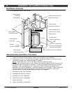
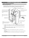
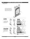
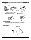
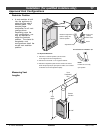
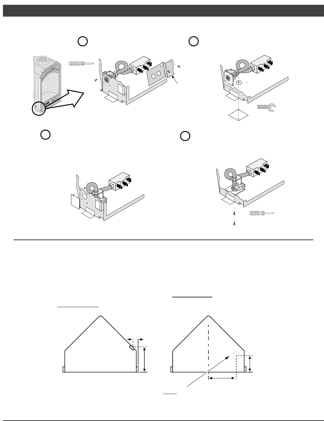
Optional Gas Line Location
Remove the two screws near the
gas inlet (save these screws).
Phillips
Screwdriver
5/16" Wrench
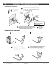
Remove the cover plate on the bottom
of the fireplace (save these nuts).
Secure the gas inlet assembly using
the screws removed in step “a”.
a
b
Phillips
Screwdriver
d
c
Position the gas inlet assembly over the hole in
the baseplate (do not secure at this time).
Position the cover plate over the gas inlet hole on
the left side of the fireplace and secure using the
nuts removed in step “b”.
HINT: remove the
control cover for
easier access.
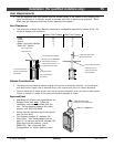
Electrical Connection
• Make sure the household breaker is shut off prior to working on any electrical lines.
• The fireplace must be properly grounded in accordance with local codes (or ANSI/NFPA 70-1987)
• The electrical line must be 14 gauge, and supply 120 Volts at 60 Hz (2 Amps)
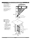
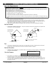
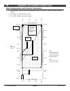
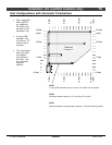
Electrical Line Location
Optional Location
The optional electrical inlet is flush
with the base of the fireplace.
NOTE: a 3-1/2" diameter hole is required to
provide clearance for the electrical inlet screws.
5-3/8"
3-1/8"
1-3/4"
7"
Standard Location