8
275
FIG
. 2.11
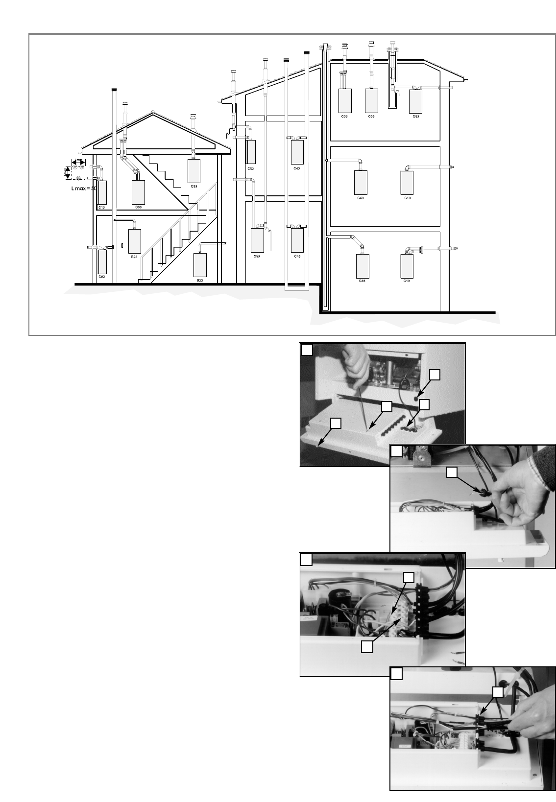
2.10. ACCESSORY CONNECTION
To carry out the connection for the roomstat or the outdoor sensor,
proceed as follows:
1. Unscrew the screws “A” and rotate the control panel forwards;
2. Insert the connection cable for the thermostat or the outdoor
sensor into the cable gland “B” and open the lid of the control
panel after having first unscrewed fastening screws “C”.
3. Insert the connecting cable into the cable clamp “D” shown in
the figure and fasten it.
4. Remove the grommet “E” shown in the figure, make a hole in it
and pass the connecting cable for the roomstat or the outdoor
sensor through it.
5a. In order to connect up the roomstat, remove the link that is
located in the “F” terminal (marked with the initials “TA”) and
connect the cables.
5b. To connect up the outdoor sensor, insert the cables into the “G”
clamp (marked with the initials “SE”).
6. Return the grommet “E” to its initial position, then close back
the lid and lastly return the control panel to its place.
7 If a remote time clock is to be fitted, disconnect the integral time
clock plug from the P.C.B.
8 Using a volt-free switching time clock, connect the switching
wires from the time clock following points 1-6 above.
9 If using a time clock and room thermostat, these must be
connected in series as per points 1-8 above.
Note: Only a two-wire type room thermostat can be used.
For details on fitting the D.H.W. probe (ecoGENUS 27
RFFI only), please consult the separate instruction
sheet supplied with the probe.
An anti-frost device is built-in to the appliance’s
electronic regulation system.
1
2.10.1. ROOM THERMOSTAT CONNECTION
2
3
4
B
D
A
C
E
F
G
E


