14
275
3.5. DISPLAY:MESSAGES SHOWN DURING
N
ORMAL OPERATION
3.6. OPERATING PARAMETERS
3.6.1. CONTROL
MODES
During operation of the boiler, while it is carrying out its normal
operations, the left-hand display shows a series of characters that
refer to the operations indicated below:
--
Diagnostics phase (precedes the other operations)
00
No request for heat
CC
Heating, burner off
CC..
Heating, burner on
cc
Pump overrun for heating
dd
Domestic hot water, burner off
dd..
Domestic hot water, burner on
hh
Pump overrun for domestic hot water
bb
Storage cylinder, burner off (SYSTEM version)
bb..
Storage cylinder, burner on (SYSTEM version)
N
OTE: the flashing dot on the left-hand display always indicates
“burner off”; if the still dot indicates “burner on”.
The right-hand display (two-digit) shows:
- in HEATING mode: temperature of the heating system flow;
- in DOMESTIC HOT WATER mode: temperature of domestic hot water.
The boiler has been designed to allow easy intervention with regard
to the operating parameters.
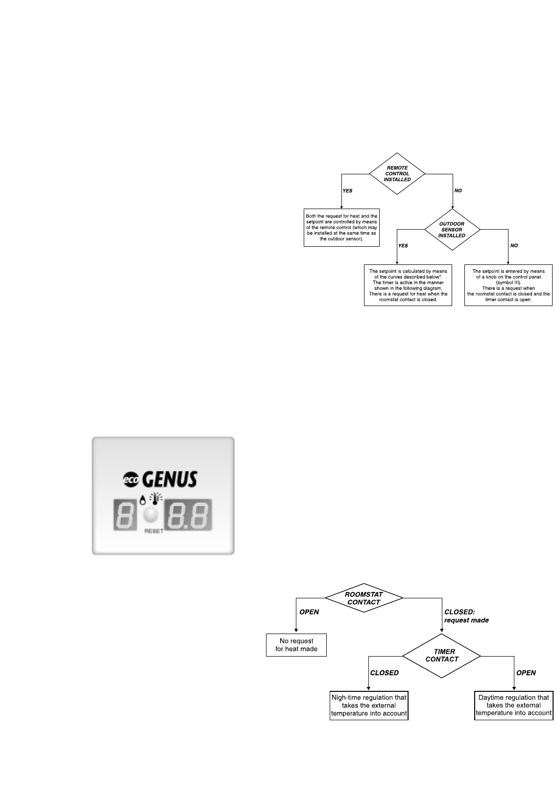
The generation of the set-point and the request for heat are clarified
in the following diagram, with regard to the heating mode.
* See section 3.6.2.
The remote control and the timer are available as an accessory Kit:
in the preceding diagram, it is clear that in the event that a device of
this type is not installed, the calculation of the set-point depends on
an outdoor sensor (if installed) and is carried out by the P.C.B.
N
OTE
: a configuration is also possible which allows for the
simultaneous presence of a remote control and an outdoor sensor. In
this case, the flow temperature is calculated as a function of the
external temperature and the room temperature. In this manner, it is
possible to carry out a particularly efficient modulation, which allows
considerable comfort to be obtained, combined with savings in fuel.
The influence of the roomstat and the timer are shown in the
following diagram, taking into consideration the fact that:
- ON/OFF Room thermostat installed: contact open or closed,
controlled by the room thermostat temperature sensor.
- ON/OFF Room thermostat not installed: contact closed (jumper).
- Timer installed: contact open or closed, controlled by the timer
settings entered by the user.
- Timer not installed: contact open.
LEFT RIGHT
- the gas cock is closed;
- the electrical connection has been carried out in the correct
manner. To allow the air to escape from the system, proceed as
follows:
- turn on the On/off knob “D” and position the selector knob “A” in
the “winter” position. The boiler pump will start up and three
consecutive attempts will be made to ignite the burner. After the
third attempt, the electronic system will shutdown the boiler,
because the supply of gas has been cut off. The message “A01”
will appear on the display;
- let the pump operate until all the air has escaped from the
system;
- repeat the procedure for bleeding the radiators of air;
- draw hot water for a short while;
- check the system pressure and, if it has gone down, fill it with
water until it returns to 1 bar.
2. Check the flue system for products of combustion.
3. Check that any required local ventilation inlets are open.
4. Fill the boiler condensate trap with water.
N.B. In the event of prolonged period of system shutdown,
the condensate trap should be filled before any renewed use.
A shortage of water in the trap is dangerous because it could
possibly lead to a leakage of fumes into the air.
5. Turn on the gas cock and check the seals on the connections,
including the one for the burner, making sure that the meter does
not signal the passage of gas. Check the connections with a soap
solution and eliminate any leaks.
6. Press the reset button “H” for the lighting system; the spark will
light the main burner. If the burner does not light the first time,
repeat the procedure.
The boiler is configured in the factory for the gas type in
question. It is not necessary to regulate the gas type on
installation.
N
OTE: the reference values of the CO
2
are contained in the
T
ECHNICAL INFORMATION
section on page 4.
Schematic representation of the influence exerted by the roomstat
and by the timer on the request for heat and on the calculation of the
set-point (flow temperature of the primary circuit) by means of the
external temperature values:


