11
275
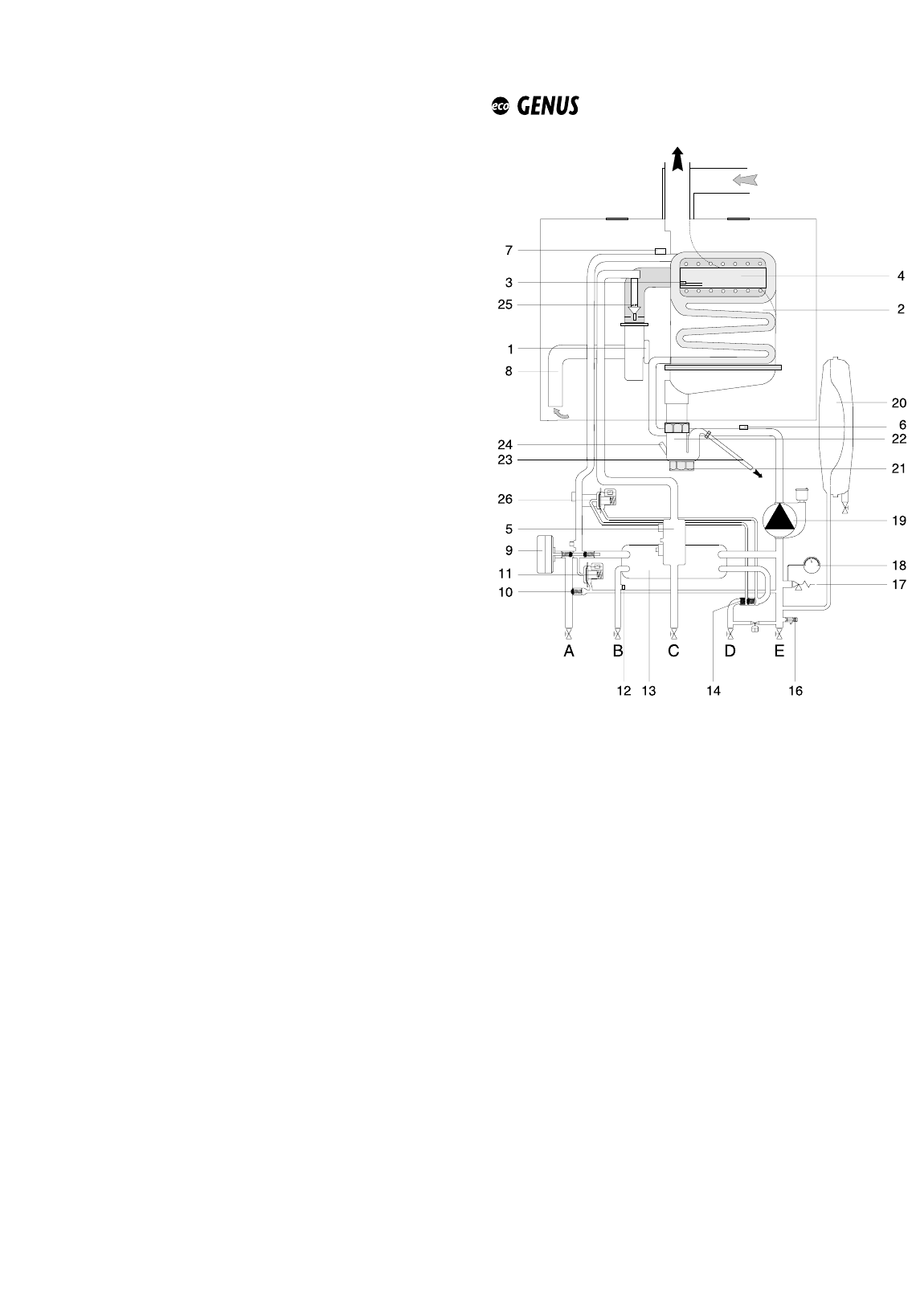
2.12. WATER CIRCUIT DIAGRAMS
LEGEND:
1- Fan
2 - Main Heat exchanger
3 - Ignition/detection electrode
4 - Burner
5 - Gas valve
6 - Heating return temperature probe
7 - Heating flow temperature probe
8 - Silencer
9 - Motorised valve
10 - Automatic by-pass
11 - Main circuit flow switch
12 - Domestic hot water temperature probe
13 - Secondary heat exchanger
14 - Domestic hot water inlet filter
16 - Drain valve
17 - Safety valve
18 - Pressure gauge
19 - Circulation pump with automatic air release valve
20 - Expansion vessel
21 - Condensate trap inspection cap
22 - Condensate trap
23 - Condensate discharge tube
24 - Condensate trap inlet
25 - Injector
26 - Domestic hot water flow switch
24 MFFI
C3 = CONNECTION TO ROOMSTAT
1: Input - 1
2: Input - 2
C4 = TIMER
1: 3 V output
2: Timer ground
3: Timer output
4: Not connected
C5 = REMOTE CONTROL (Bus+/Bus-)
1: Input/output-1
2: Input/output-2
C6 = SENSOR CONNECTOR
1: Domestic hot water flow switch (grey)
2: Main circuit flow switch (grey)
3: Under floor heating thermostat (grey)
4: Heating flow sensor (grey)
5: Heating return sensor (grey)
6: Domestic hot water sensor (grey)
7: Not used: jumper
8: Outdoor sensor (grey)
9: Domestic hot water flow switch (grey)
10: Main circuit flow switch (grey)
11: Under floor heating thermostat (grey)
12: Flow sensor (grey)
13: Heating sensor (grey)
14: Domestic hot water sensor (grey)
15: Not used: under floor heating
16: Outdoor sensor (grey)
C7 = EQUIPMENT CONNECTIONS
1: Secondary output (optional)
2: Gas valve (white)
3: 3-way valve neutral (white)
4: Pump (white)
5: Ionisation (black)
6: Not connected
7: Ground
8: Pump earth (yellow/green)
9: Secondary output (optional)
10: Gas valve (brown)
11: 3-way valve (domestic hot water) (brown)
12: 3-way valve (heating) (brown)
13: Pump (brown)
14: Not connected
15: Earth
16: Gas valve earth (yellow/green)


