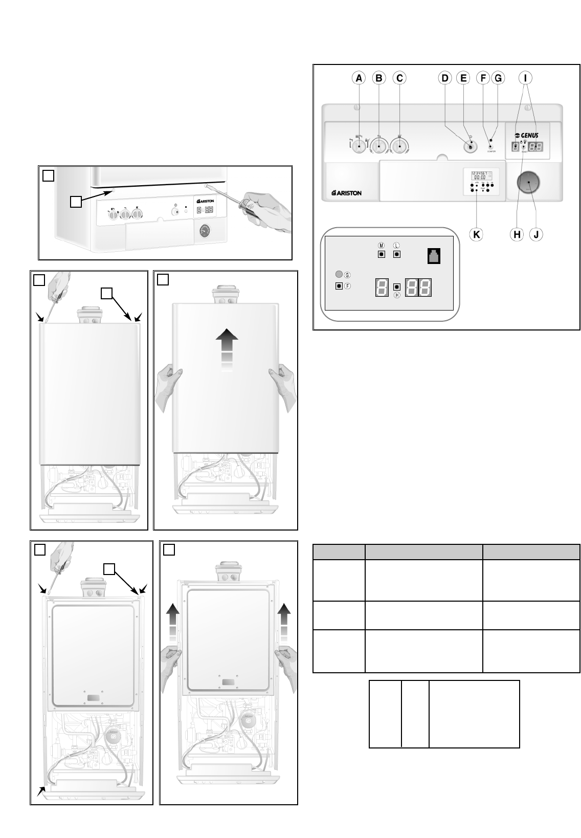
3.3. CONTROL PANEL
A. Selector Knob for Summer/Winter/Flue Test Modes
B. Domestic Hot Water Temperature Adjustment Knob
C. Central Heating Temperature Adjustment Knob
D. On/Off L.E.D.
E. On/Off Knob
F. “COMFORT” Function Push-button/heating only (RFFI SYSTEM)
G. “COMFORT” Function L.E.D./heating only (RFFI SYSTEM)
H. Reset Button
I. Multifunction Display
J. Heating System Pressure Gauge
K. Time Clock
L. Programming “+” key
M. Programming “-” key
When necessary configure the main P.C.B. according to the following
diagram (please refer to the legend on page 17)
I = inserted (contact closed)
N.I = not inserted (contact open)
SECONDARY OUTLET = conntection C7 (position 1-9 page 17)
1. Make sure that:
- the cap of the automatic air release valve is loosened;
- the system pressure is at least 1 bar on the pressure gauge;
3.4. INITIAL START-UP
3.2. REMOVING THE CASING
To disassemble the front casing panel, follow these steps:
1. Unscrew the screws “A” (1/4 turn only) and rotate the control
panel forwards;
2. Unscrew the screws “B”;
3. Unhook the front panel of the casing by lifting it.
To disassemble the side panels, follow these steps:
4. Unscrew the screws “C” (at bottom) fastening the side panels;
5. Lift and unhook the panels.
13
275
A
1
B
2
3
C
4 5
POSITION
3
4
5
INSERTED
Secondary outlet (connection
C7; positions 1-9) controls a
LPG valve (optional).
Continuous pump operation.
Secondary output relates to a
secondary pump (optional).
NOT INSERTED
The secondary outlet
controls what is
selected by Jumper 5.
No change in pump
operation.
Secondary output
controls a zone valve
(optional)
7
N.I.
I.
N.I.
I.
8
N.I.
N.I.
I.
I.
CONFIGURATION
Central heating only
MFFI
Not used
RFFI System


