7
275
In F
IG. 2.11 below, several different types of flue systems are shown.
For additional information regarding the flue accessories, please
consult the Flue Pipe Accessories manual.
Coaxial
Systems
Twin Pipe
Systems
Exhaust Type
C
13
B
33
outlet of fumes in
chimney or exhaust flue
C
13
, C
33
, C
43
C
53,
C
83
B
23
Maximum Extension
Exhaust/Air
(m)
4
4
31 (S1=S2)
55 (S1+S2)
54 (S2)
Diameter
of Pipes
(mm)
Ø 60/100
Ø 60/100
Ø 80/80
Ø 80/80
Ø 80
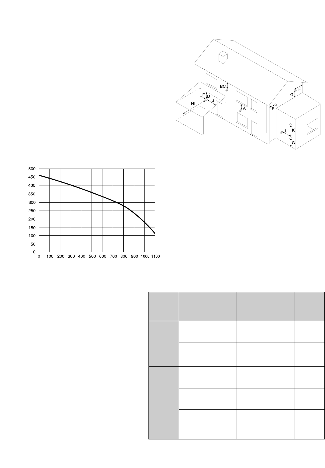
TERMINAL POSITION mm
A - Directly below an open window or other opening 300
B - Below gutters, solid pipes or drain pipes 75
C - Below eaves 200
D - Below balconies or car-port roof 200
E - From vertical drain pipes and soil pipes 75
F - From internal or external corners 300
G - Above ground or below balcony level 300
H - From a surface facing a terminal 600
I - From a terminal facing a terminal 1200
J - From an opening in the car port
(e.g. door, window) into dwelling 1200
K - Vertically from a terminal in the same wall 1500
L - Horizontally from a terminal in the same wall 300
FIG. 2.6
2.9. FLUE CONNECTIONS
FLUE SYSTEM
The provision for satisfactory flue termination must be
made as described in BS 5440-1.
The appliance must be installed so that the flue terminal is
exposed to outdoor air.
The terminal must not discharge into another room or
space such as an outhouse or lean-to.
It is important that the position of the terminal allows a
free passage of air across it at all times.
The terminal should be located with due regard for the
damage or discolouration that might occur on buildings in
the vicinity.
In cold or humid weather water vapour may condense on
leaving the flue terminal.
The effect of such “steaming” must be considered.
If the terminal is less than 2 metres above a balcony,
above ground or above a flat roof to which people have
access, then a suitable terminal guard must be fitted.
When ordering a terminal guard, quote the appliance
model number.
A suitable terminal guard is available from:
TOWER FLUE COMPONENTS
Morley Road
Tonbridge
Kent TN9 1RA
R
ESIDUAL HEAD OF THE BOILER
expansion and add an additional sealed expansion vessel with
adequate capacity.
MAINS WATER FEED - CENTRAL HEATING:
There must be no direct connection to the mains water supply
even through a non-return valve, without the approval of the Local
Water Authority.
F
ILLING:
A temporary method for initially filling the system and replacing
lost water during servicing and initial filling (in accordance with
Water Supply Byelaw 14), is provided as an integral part of the
connection kit (see F
IG. 2.5). The flexible hose must be removed
once the system has been filled. The D.H.W. inlet valve on the
connection kit has two positions, one for winter and one for the
summer. This enables the flow-rate through the appliance to be
adjusted so that a sensible D.H.W. temperature may be achieved
throughout the year.
D
OMESTIC W
ATER
The domestic water must be in accordance with the relevant
recommendation of BS 5546:1990. Copper tubing to BS EN
1057:1996 is recommended for water carrying pipe work and
must be used for pipe work carrying drinking water.
The minimum acceptable spacing from the terminal to obstructions
and ventilation openings are specified in Fig. 2.6


