17
275
3.7.2. SETTING THE TEMPERATURE FIELD
Remove the protection of the display using a screwdriver as a lever.
Press the reset button for over 5 seconds. The display will show
“
AA0033
”. On pressing the reset button again the display will change to
“
RR0000
” (R indicates the setting of the field of regulation of the flow
temperature). Using the button “E”, the setting may be changed. It is
possible to choose two fields of regulation of the flow temperature.
“
0000
” signifies that the flow temperature (which may be set by means
of the knob on the front control panel) may be regulated from 30 to
75°C. “
0011
” signifies that the flow temperature (which also may be set
by means of the knob on the front control panel) may be regulated
from 42 to 82 °C. The factory setting is “
0000
”.
The boiler allows the convenience level to be increased in the output
of domestic hot water by means of the “COMFORT” function. This
function keeps the secondary exchanger warm during the periods in
which the boiler is inactive, thereby allowing the initial water drawn to
be at a higher temperature. The function may be activated by
pressing the “H” key on the control panel (see section 3.3.). When
the function is active, a green light comes on, again located on the
control panel.
N
OTE: During the overrun period of the pump, the “COMFORT”
function, if selected, is temporarily deactivated. The L.E.D. light
remains on to indicate that the boiler will return to the “COMFORT”
mode once the pump overrun is terminated.
This function may be activated by pressing the “H” key on the
control panel (see section 3.3.). When the function is active, a green
light comes on, again located on the control panel. This indicates that
the external indirect cylinder is not maintained at the set temperature,
only the anti-frost protection of the indirect cylinder is active. When
the temperature goes below 5°C, the boiler turns itself on and heats
up the indirect cylinder until the temperature goes over 10°C.
H
EATING ONLY KEY:
24 RFFI
3.7. REGULATIONS
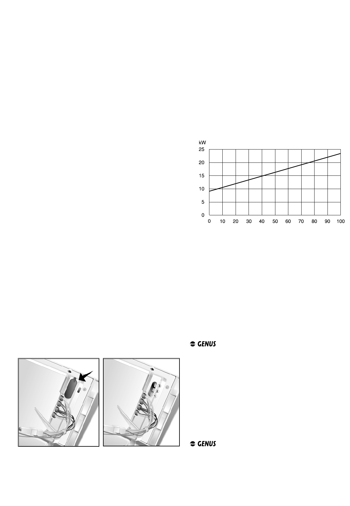
To access the areas reserved for the regulation and control, open the
control panel, after having first unscrewed the plastic fastening
screws, and raise the rubber protection stopper for the
potentiometers, as shown in the illustration.
This allows access to the three regulation potentiometers:
1. RA - Ignition delay (anti-cycling device) potentiometer
It is possible to set the ignition delay by adjusting the
potentiometer with a screwdriver. The values that may be
selected range from 0 to 15 min.
The delay has been set at 15 minutes in the factory. The value
D
ISPLAY MESSAGE REFERENCE
3.7.1. P
OTENTIOMETERS
The boiler is designed to monitor some operating variables and
settings by means of the display on the front control panel. Keeping
the reset key pressed for over 10 seconds allows access to the
“readout” function of the main system variables. By pressing the
button repeatedly after that, it is possible to read the following
information in sequence:
Indication on the
left-hand display
UU//11
UU//22
UU//55
UU//FF
UU//tt
PP//AA
PP//--
PP//LL
bb
ll
Value read on right-hand display
Flow temperature of the heating circuit (C°)
Return temperature of the heating circuit (C°)
Domestic hot water output temperature (C°)
Ionisation current (expressed in bT)
Main circuit flow switch
Heating ignition delay (see section 3.6.4. -
expressed in min.x10)
Maximum thermal power for heating (expressed
in a percentage of the difference between the
maximum power allowed by the boiler and the
minimum)
Soft light power (expressed in a percentage of
the difference between the maximum power
allowed by the boiler and the minimum)
Last safety shut-off (see section 3.7.)
Last shutdown (see section 3.7.)
3.6.3. SETTINGS DISPLAY
To return to the normal display, press the “H” reset key repeatedly
until all the sequence of “readout” functions have scrolled through the
display and until one of the “display of normal operations” has
appeared (the message that appears will depend on the current
operating mode of the boiler).
* N
OTE 1: U/1 means that “
uu
”and “
11
” blink alternately on the display
N
OTE 2: the value 100% appears as “
0000
” on the display
entered may be viewed in the manner described in section 3.6.3.
(the display shows the value with steps of 10).
2. PR - Maximum heating circuit power potentiometer, variable
between the maximum allowed by the boiler and the minimum
(see “T
ECHNICAL INFORMATION” table). The boiler is calibrated in
the factory at 70%.
3. RLA - Soft-light potentiometer, variable between the
maximum power (shown on the display as “
0000
”, i.e. 100%) and
minimum power (shown on the display as “
0011
”, i.e. 1%). The boiler
is calibrated in the factory at a value which is suitable for ignition
with any type of gas (approx. 70%).
The display shows the value between 100% (“
0000
” on the display)
and 1% (“
0011
”) of this interval. The indications on the display with
regard to the power are shown in the graph:
3.7.3. COMFORT KEY:
24 MFFI


