


73InRoom Precision AC Tech Data Manual
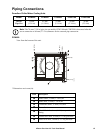
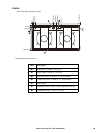
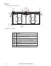
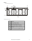
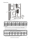
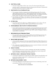
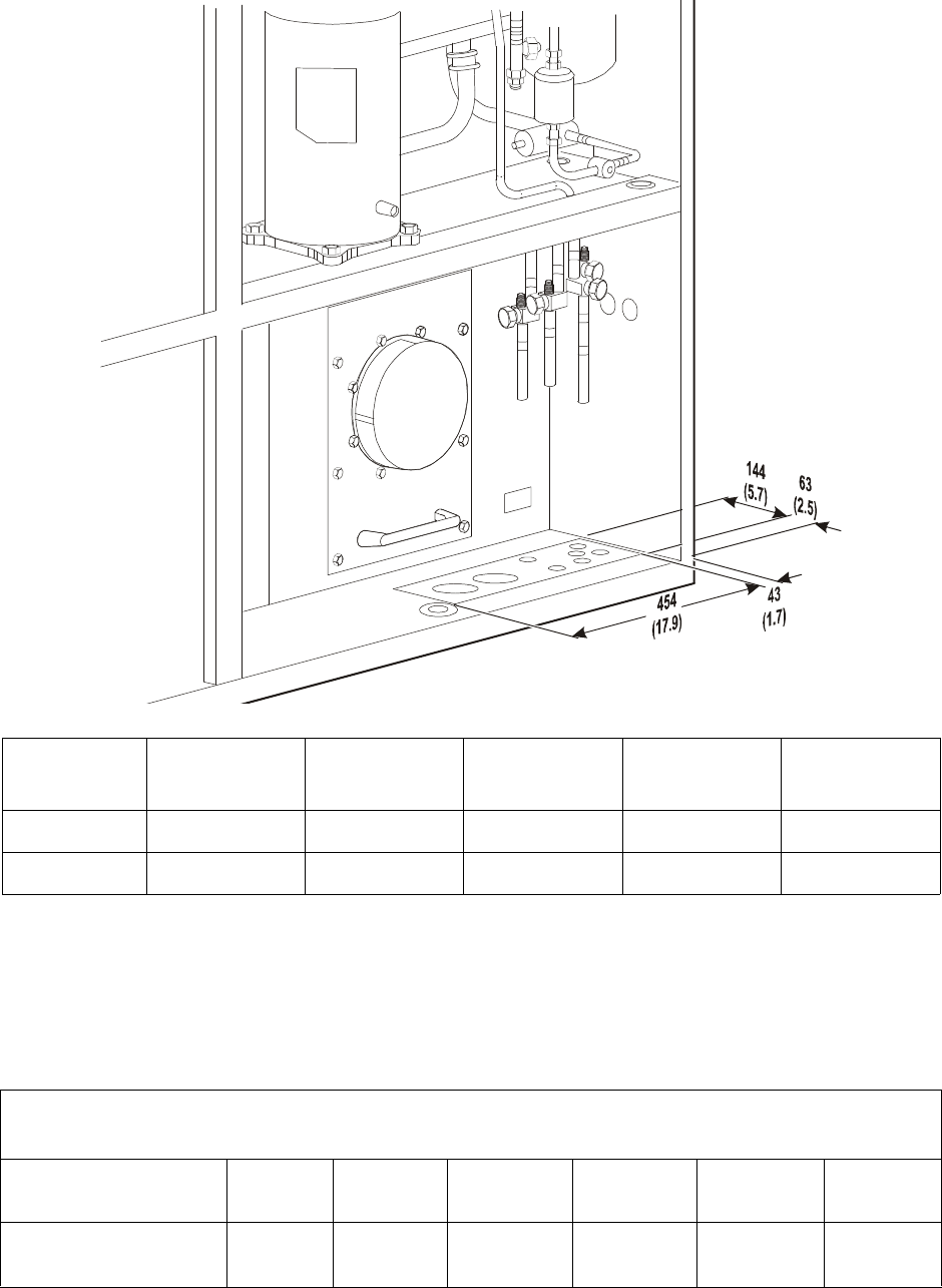
Refrigerant Piping
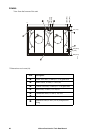
Dimensions in mm (in).
Considerations
The refrigerant connections are located near the compressor and are labelled pressure pipe and liquid
pipe. Models containing two circuits will be labelled pressure pipe 1 and pressure pipe 2.
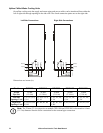
To ensure oil return in ascending hot gas lines, particularly at partial load, the minimum refrigeration
capacity must not fall below the value on the table below.
The horizontal lines must always be routed with a slope towards the condenser.
Establish the shortest route for pipework from the unit to the condenser.
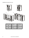
Model
PA211
1 circuit
PA311
1 circuit
PA452
2 circuits
PA612
2 circuits
PA862
2 circuits
Pressure Line 16 mm (5/8 in) 22 mm (7/8 in) 16 mm(5/8 in) 22 mm (7/8 in) 22 mm (7/8 in)
Liquid Line 12 mm (1/2 in) 16 mm (5/8 in) 22 mm (7/8 in) 16 mm (5/8 in) 16 mm (5/8 in)
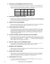
Minimum refrigeration outputs required for oil transportation in rising pressure lines for
R407C refrigerant at dew point of 48°C (118.4°F)
Pipe Diameter
mm (in)
15 (5/8) 18 (3/4) 22 (7/8) 28 (1 1/8) 35 (1 3/8) 42 (1 5/8)
Refrigerant Capacity
kW (MBH)
4.41 (15) 5.17 (17.7) 7.14 (24.4) 10.0 (34.2) 16.58 (56.6) 25.9 (88.4)
n
a
3
0
5
1
a