


77
77
7
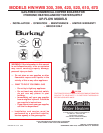
1. CONVENTIONAL INSTALLATIONS
All modern hydronic type boilers are exceptionally fast heating units.
The low water volumes in relation to firing rates require special
attention to water flow rates for smooth, efficient operation. These
considerations for the A. O. Smith copper heat exchanger boilers
are covered below.
Conventional 10
0
C (20
0
F) drop in systems for a fully loaded boiler
will maintain the following approximate flow rates:
U.S. CANADIAN
MODELS MODELS LPM GPM
HW-300 HWB-300 87 23
HW-399 HWB-399 114 30
HW-420 HWB-420 132 35
HW-520 HWB-520 148 39
HW-670 HWB-610 175 46
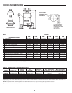
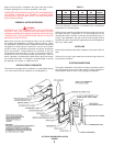
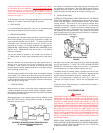
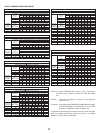
Figure 1 shows a typical installation of the boiler with pipe sizing
and circulator selected by the installer to provide adequate water
flow whenever the boiler is firing.
In a system with several large zones of which any might be smaller
than approximately 1/3 of the system should include a hydronic
balancer as shown in fig. 1. The balancer connects between the
system supply and the return line before the circulator inlet.
Adjustment of the balancing cock should permit adequate boiler
flow rate when only the smallest zone is in operation.
Attention should be given to balancing inputs and water flow rates
where wide variations of system flow rates can occur.
The recommended minimum flow rates that will result in
approximately 30
0
C (50
0
F) temperature rise across the boiler are
as follows:
U.S. CANADIAN
MODELS MODELS LPM GPM
HW-300 HWB-300 34 9
HW-399 HWB-399 45 12
HW-420 HWB-420 53 14
HW-520 HWB-520 61 16
HW-610 HWB-610 69 18
HW-670
76 20
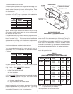
If system flow rate is unknown, or if zoning creates extreme
variations in flow rates, the boiler should be installed as shown
in fig. 2 for A. O. Smith
LINEAR-TEMP installations.
2.
LINEAR-TEMP INSTALLATIONS
A. New Installations
A. O. Smith
LINEAR-TEMP systems have been designed to provide
efficient, trouble-free operation of the boiler sizes covered in this
manual with any of the following conditions:
a. Unknown system flow rate
b. Varying flow rate as with zoned systems
c. Multiple boiler installations
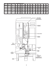
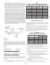
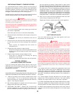
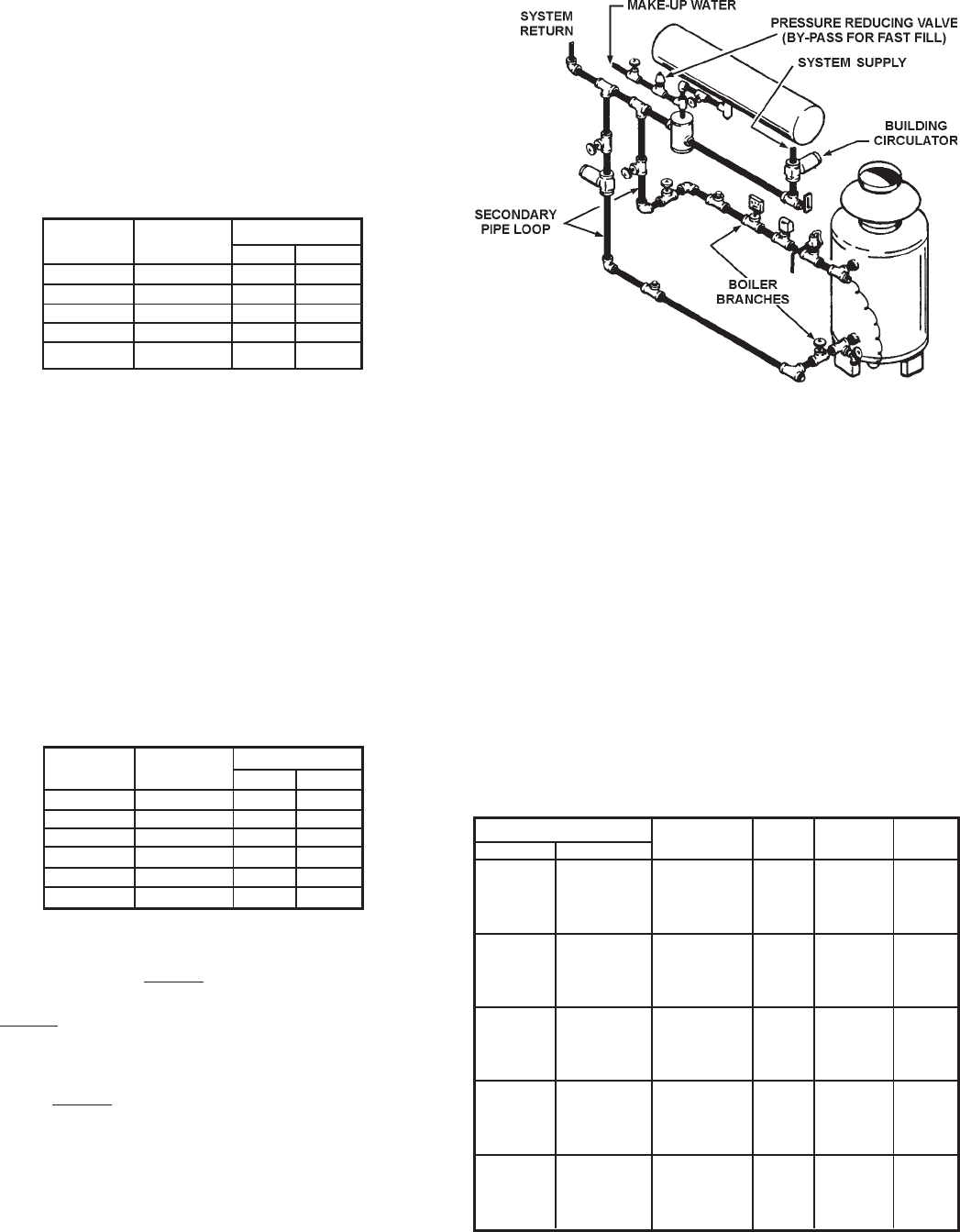
Figure 2 shows piping and accessory arrangement for a boiler
pumped independent of the primary system mains. Pipe sizing
and boiler loop pump selection data are shown in Table 5 for
several different temperature rises across the boilers.
ONE BOILER INSTALLED
INDEPENDENT OF THE PRIMARY SYSTEM
FIGURE 2
Total heating requirements for the building can be supplied by a
series of boiler loops all connecting to a common pipe joining the
system supply and return mains. The supply and return branches
of each boiler loop must join the common pipe only a short nipple
length apart. The different sets of branches should be installed
reasonably close together, but not necessarily to the short nipple
length as required for the supply and return of each set. These
branches may be made with tees or with welded connections.
The installer is reminded that the total boiler flow rates need not
match the system flow rate.
TABLE 5
PUMP AND PIPE SIZING DATA
(PIPING FROM TEES IN MAIN TO BOILER BRANCHES)
Quantity and Model Temp. *Pump Pipe
U.S Canadian Rise°C (°F) G.P.M. Size Size
10 (20) 23 1-1/2"PR 2"
HW-300 1 HWB-300 15 (30) 15 150 1-1/2"
15 (30) 15 125 1-1/4"
20 (40) 11 100 1"
10 (20) 30 60-13 2"
HW-399 1 HWB-399 15 (30) 20 1-1/2"HV 1-1/2"
20 (40) 15 150 1-1/2"
20 (40) 15 125 1-1/4"
10 (20) 32 60-13 2"
HW-420 1 HWB-420 15 (30) 21 1-1/2"HV 1-1/2"
20 (40) 16 150 1-1/2"
20 (40) 16 125 1-1/4"
10 (20) 39 2-1/2" 2-1/2"
HW-520 1 HWB-520 10 (20) 26 1-1/2"HV 2"
17 (35) 23 1-1/2"HV 1-1/2"
20 (40) 20 150 1-1/2"
10 (20) 51 60-13 3"
HW-670 1 HWB-610 15 (30) 34 2-1/2" 2-1/2"
17 (35) 29 2" 2"
20 (40) 25 1-1/2"HV 1-1/2"
NOTE: Pipe loop sizes and pump selections based on
50 equivalent feet of pipe and fittings.
*All pump sizes listed are B & G model numbers.