


1313
1313
13
After it has been determined that each appliance remaining
connected to the common venting system properly vents when
tested as outlined above, return doors, windows, exhaust fans,
fireplace dampers and any other gas burning appliance to their
previous conditions of use.
Any improper operation of the common venting system should be
corrected so the installation conforms with the latest edition of
CAN/CGA B149.1-00 (latest edition). When resizing any portion of
the common venting system, the common venting system should
be resized to approach the minimum size as determined using
the appropriate tables in Appendix G in CAN/CSA B149.1-00.
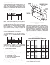
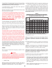
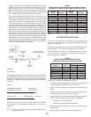
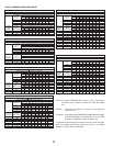
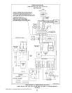
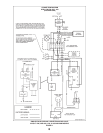
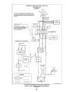
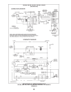
4. MULTIPLE VENT TABLE
Table 9 has been compiled to show the material sizes in a Type B
doublewall combined vent system. Refer to
CAN/CSA B149 .1-00 (latest edition), or the ASHRAE
1983
Equipment Volume for further information.
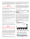
A combined vent system is one in which two or more boilers at one
level are attached to a common vent.
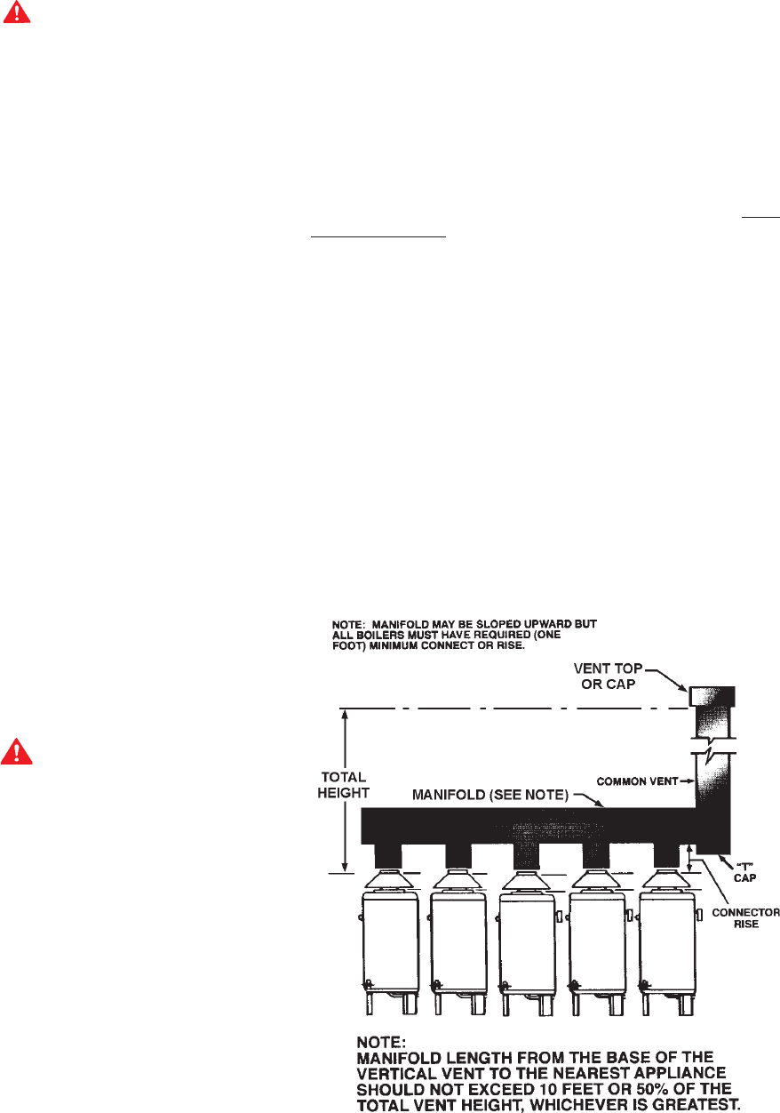
In order to use table 9, the connector rise and total vent height
must be known. Connector rise is vertical distance from the draft
hood outlet to the point where the manifold connection is made.
Total vent height is the least vertical distance from a draft hood
outlet to the top of the vent. Local codes or utility requirements
often govern termination height. ULC listed doublewall gas vents,
up through 24" (610mm) diameter, can be installed in heated and
unheated areas and can pass through floors, ceilings, partitions,
walls and roofs, provided the required one inch clearance is
observed. These vents should be installed in accordance with
CAN/CSA B149.1-00 (latest edition).
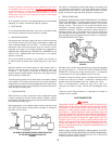
EXAMPLE SHOWING USE OF THE HWB/HW-610 COMBINED VENT
SIZING TABLE 9
FIGURE 8
Where a continuous or intermittent back draft is found to exist the
cause must be determined and corrected. A special vent cap may
be required. If the back draft cannot be corrected by the normal
methods or if a suitable draft cannot be obtained, a blower type
flue gas exhauster may be employed to ensure proper venting and
correct combustion if permitted by local codes.
WARNING
FAILURE TO CORRECT BACK DRAFTS WILL CAUSE AIR
CONTAMINATION AND UNSAFE CONDITIONS.
Vent connectors serving appliances vented by natural draft shall
not be connected into any portion of mechanical draft systems
operating under positive pressure.
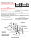
3. CONNECTING BOILER TO A COMMON VENT
Do not connect the boiler to a common vent or chimney with solid
fuel burning equipment. This practice is prohibited by many local
building codes as is the practice of venting gas fired equipment to
the duct work of ventilation systems.
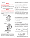
Where a separate vent connection is not available and the vent
pipe from the boiler must be connected to a common vent with oil
burning equipment, the vent pipe should enter the common vent
or chimney at a point ABOVE the flue pipe from the oil fired unit.
Where two or more appliances vent into a common vent connector
or manifold, the area of the common vent or vent connector should
at least equal the area of the largest vent connector plus 50% of
the areas of the additional draft hood outlets.
When removing a boiler from a system with a common vent, use
the following steps:
Be sure the other appliances connected to the common vent are
not in operation.
Seal any unused openings in the common venting system.
Visually inspect the venting system for proper size and horizontal
pitch and determine there is no blockage or restriction, leakage,
corrosion and other deficiencies which could cause an unsafe
condition.
WARNING
Ensure sufficient supply and ventilation air. Under no circumstances
should the equipment room where the boiler is installed ever be
under negative pressure. Insufficient air supply can interfere with
combustion and ventilation of this boiler resulting in unsafe
conditions.
Insofar as is practical, close all building doors and windows and
all doors between the space in which the appliances remaining
connected to the common venting system are located and other
spaces of the building. Turn on clothes dryers and any appliance
not connected to the common venting system. Turn on any exhaust
fans, such as range hoods and bathroom exhausts, so they will
operate at maximum speed. Close fireplace dampers.
Place in operation the appliance being inspected. Follow the
lighting instructions. Adjust thermostat so appliance will operate
continuously.
Test for spillage at the draft hood relief opening after five minutes
of main burner operation. Use the flame of a match or candle.