


5151
5151
51
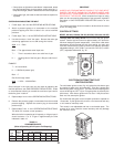
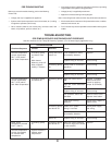
• If lamp does not light when reset button is depressed, attach
the test flashlight leads to the protector switch terminals. If
lamp does not light, switch is defective and must be replaced.
• If lamp does light, the leads are bad and must be repaired or
replaced.
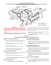
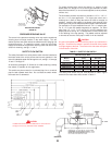
CHECKING AND ADJUSTING THE INPUT
1. Follow steps 1 thru 6 of the OPERATING INSTRUCTIONS.
2. Attach a pressure gauge or a manometer to the manifold
pressure tapping and refer to table 8 for correct manifold
pressure.
3. Follow steps 7 thru 11 of the OPERATING INSTRUCTIONS.
4. Use this formula to “clock” the meter. Be sure that other gas
consuming appliances are not ON during this interval.
3600 x H = Btuh
T
Btuh = The approximate actual input rate.
T = Time in seconds to burn one cubic foot of gas.
H = Heating value of the fuel gas in Btu per cubic foot of
gas.
EXAMPLE:
T = 9.0 seconds/ft
3
H = 1050 Btu/ft
3
(natural gas)
Btuh = ?
Gas flow through meter:
3600 x 1050 = 420,000 Btuh
9.0
Small changes in the input rate may be made by adjusting the
manifold pressure, see GAS PRESSURE REGULATORS. Under
no circumstances should you exceed the maximum input rate for
the boiler given in table 2.
5. Repeat steps 1 thru 6 of the OPERATING INSTRUCTIONS.
6. Remove the pressure gauge or manometer from the manifold
pressure tapping. Replace the screw-in plug in the manifold
pressure tap.
7. Repeat steps 7 thru 11 of the OPERATING INSTRUCTIONS.
The boiler will resume normal operation.
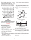
When the boiler is operating at full capacity, or full gas input, it
should consume 1 cu. ft. of gas in approximately the time
indicated in table 10.
TABLE 10
CONSUMPTION RATE
(Refer to Operating at Full Input or Full Capacity)
TIME TO CONSUME 1 CU. FT.
Heating OF GAS (SECONDS)
Type Value HWB/ HWB/ HWB/ HWB/ HWB/ HWB/
Gas Btu/Ft.^3 HW-300 HW-399 HW-420 HW-520 HW-610 HW-670
Natural 1050 12.6 9.5 9.0 7.3 6.2 5.7
Propane 2500 30.0 22.6 21.4 17.3 14.8 13.4
IMPORTANT
UNDER NO CIRCUMSTANCES SHOULD THE GAS INPUT
EXCEED THE INPUT SHOWN ON THE BOILER MODEL AND
RATING PLATE. OVERFIRING COULD RESULT IN DAMAGE OR
SOOTING OF THE BOILER.
Minor variances from input on rating
plate can be corrected by adjustment of gas pressure regulators
described in GAS PRESSURE REGULATORS section of this
manual.
The inlet gas pressure must not exceed or be less than the values
shown on rating plate.
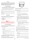
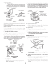
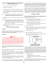
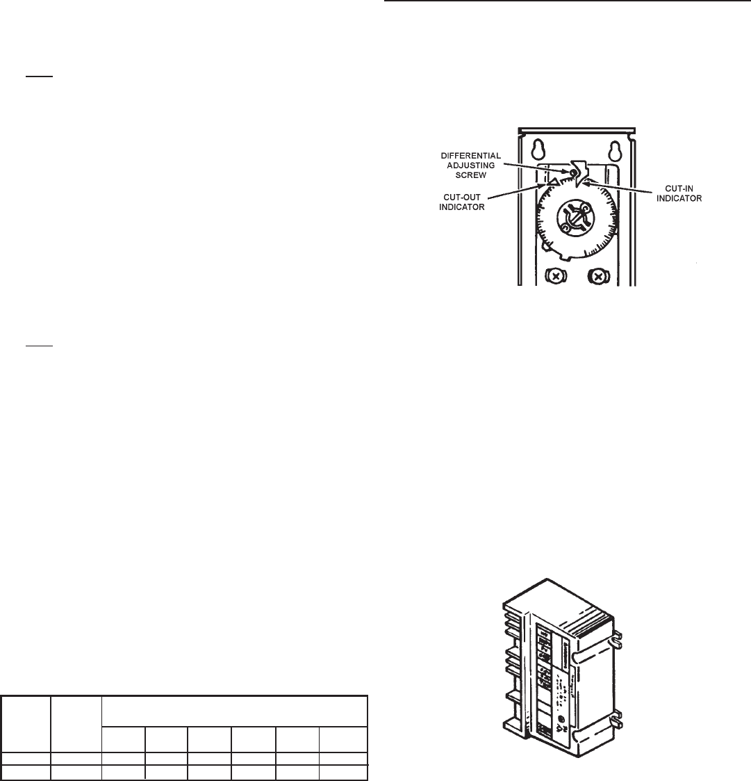
CONTROL SETTINGS
MODEL HW-300, HW-399, HW-420, HW-520, HW-610 & HW-670
The high limit is a safety device wired in series with the ignition
system. Set the high limit control to approximately 10
0
F above the
maximum designed system temperature. If the boiler outlet water
temperature should exceed the high limit setting, the main gas
valve will close but the circulator will continue to operate. Maximum
adjustable setting is 115
0
C (239°F) cut-out with a 3
0
C (5
0
F) to 25
0
C
(45
0
F) adjustable differential, fig. 45.
FIGURE 45
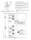
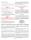
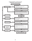
ELECTRONIC INTERMITTENT PILOT
IGNITION CONTROL
The solid state ignition control, fig. 46, ignites the pilot burner gas
by creating a spark at the pilot assembly. Pilot gas is ignited and
burns during each running cycle. The main burner and pilot gases
are cut off during the “OFF” cycle. Pilot gas ignition is proven by the
pilot sensor. Main burner ignition will not occur if the pilot sensor
does not first sense pilot ignition.
On models with the igniter control a spark continues to operate for
15 seconds. If pilot ignition fails, there is a 5 minute wait and retry
or unit must be manually reset.
This control is non-adjustable and has no serviceable parts. The
removal of its cover voids the control warranty and may damage
the electronic circuit.
FIGURE 46