


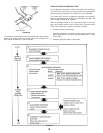
4343
4343
43
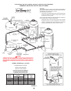
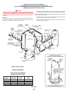
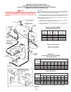
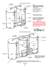
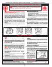
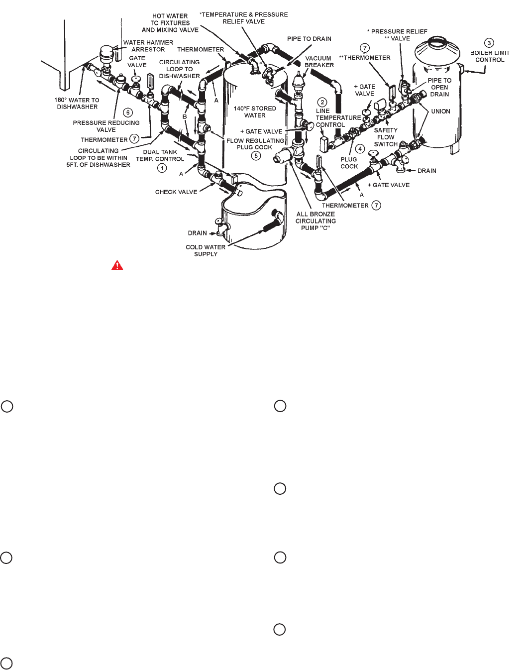
4 FLOW REGULATING PLUG COCK
(For Boiler Flow Rate Adjustment)
A slight closing of this valve may be necessary to set proper
water flow rate for 40°F temperature rise through the boiler.
Temperature rise is observed between the boiler inlet and
outlet thermometers.
5 FLOW REGULATING PLUG COCK
(For Dishwasher Recirculating Loop)
Close this valve just enough to divert sufficient flow into
circulating loop that will maintain 180°F at end of loop adjacent
to dishwasher when dishwasher is not drawing water.
6 WATER PRESSURE REDUCING VALVE
Entering water pressure to the dishwasher must be set for 20
psig flow pressure. Excessive flow pressure may waste rinse
water beyond the capacity of the boiler to maintain it at 180°F
temperature.
7 INLET/OUTLET THERMOMETERS
See A. O. Smith deliming instructions Form 4778 when normal
temperature rise between rinse thermometers starts to
increase. Thermometers should be positioned near the inlet
and outlet of the heater.
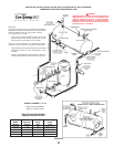
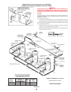
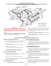
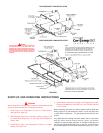
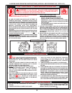
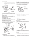
BOOSTER RECOVERY SYSTEM (PATENTED)
TWO TEMPERATURE SYSTEM WITHOUT RECIRCULATION ONE HW-300, HW-399, HW-420, HW-520,HW-610 OR HW-670
UP-FLOW MODEL COMMERCIAL BOILER WITH VERTICAL TANK
1 DUAL TANK TEMPERATURE CONTROL
The dual tank temperature control should be installed in the
lower of the two 3/4" thermostat openings in the tank.
Left Dial -High Limit
Adjust to 160°F with 20°F differential (minimum).
Right Dial -Tank Temperature
Adjust to 140°F with 8°F differential (minimum).
• May be adjusted slightly higher if total demand of
180
°
F water requires higher tank temperature.
2 LINE TEMPERATURE CONTROL
Install as close to boiler as possible. Do not insulate piping or
tee immediately adjacent to the control.
Adjust dial to 185°F with 5°F differential (minimum).
• May be set slightly higher if radiant loss from piping prevents
maintaining 180°F at dishwasher.
3 BOILER LIMIT CONTROL
(Hi Limit adjust dial 220°F with 10°F differential)
WIRING - FIGURE 24 OR 26
INSTALL IN ACCORDANCE
WITH ALL LOCAL CODES
IMPORTANT
THE INSTALLATION OF SAFETY FLOW SWITCH AS SHOWN IS REQUIRED TO
PROTECT THE BOILER IN CASE OF WATER SERVICE INTERRUPTION OR
CIRCULATOR FAILURE (A.O. SMITH PKG. NO. 211480).
+ PIPING AND FITTINGS BETWEEN GATE VALVES AND BOILERS SHOULD BE
BRASS OR BRONZE. OTHER PIPING SHOULD CONFORM TO LOCAL CODES.
GATE VALVES ARE SHOWN FOR SERVICING BOILER. HOWEVER, LOCAL CODES
SHALL GOVERN THEIR USAGE.
* PRESSURE RELIEF VALVE RATING SHOULD NOT EXCEED PRESSURE
CAPACITY OF ANY COMPONENT IN THE SYSTEM.
** INSTALL THERMOMETER AND PRESSURE RELIEF IN OPENINGS PROVIDED
ON HW-520, HW-610 & HW-670.
FIGURE 38
INSTRUCTIONS FOR NUMBERED CONTROLS SHOWN ABOVE -
DANGER
TEMPERATURE SETTING SHOULD NOT EXCEED SAFE USE TEMPERATURE AT
FIXTURES. SEE TANK TEMPERATURE CONTROL WARNING ON PAGE 32. IF
HIGHER PREHEAT TEMPERATURES ARE NECESSARY TO OBTAIN ADEQUATE
BOOSTER OUTPUT, ADD AN ANTI-SCALD VALVE FOR HOT WATER SUPPLIED TO
FIXTURES.