


5757
5757
57
TROUBLESHOOTING
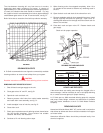
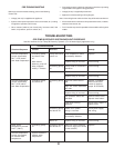
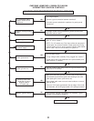
CER-TEMP 80 RECOVERY SYSTEM CHECKOUT PROCEDURE
Use this checkout for Cer-Temp 80 Recovery Systems. (For hot water supply application only)
SYSTEM OPERATION
Checkout Sequence Contact Incorrect Cause Remedy
Set tank temperature Circulating pump Pump and burner Tank temperature control Replace.
control (thermostat) and burner shut remain on. (thermostat) defective.
20°F (10°C) below off.
tank water temperature
With thermal System wiring is incorrect. Correct wiring.
balancer, pump off
delay of approx- Circulating pump Pump wired for continuous Correct wiring.
imately 2 minutes. on. operation.
Burner on. Gas valve stuck or defective. Correct or replace valve.
System wiring is incorrect. Correct wiring.
Set tank temperature Circulating pump Circulating pump High limit control set too Replace. (If problem
control (thermostat) and burner on. on. low. proven to be at this
20°F (10°C) above control by applying
tank water temperature. High limit control differential jumper to terminals.)
too wide.
System wiring is incorrect. Correct wiring.
Coil protector switch has Remove control cover,
activated. depress reset button.
Gas valve or wiring Check wiring. Repair or
defective. replace valve.
Circulating pump Power off or system Check power supply
and burner off. wiring is incorrect. and wiring.
Tank temperature control Replace.
(thermostat) defective.
Burner on. System wiring is incorrect. Correct wiring.
Boiler outlet Circulating pump Circulating pump High limit control defective, Replace.
temperature exceeds on. and burner on. or set too high (max. should
210°F (100°C). be set at 200°F).
Set tank temperature System maintains.
control (thermostat) desired water
for desired water temperature.
temperature.
PRE-TROUBLESHOOTING
Before any extensive trouble-shooting, perform the following:
Ensure That:
— Voltage (120 vac) is supplied to the appliance.
— System control (tank temperature control, thermostat, etc.) is calling
for appliance operation (call for heat).
— Other contacts (switches) are closed (relay, low water cutoff, flow
switch, coil protector, pressure switch, etc.).
— Gas supply pressure is within the maximum and minimum operating
ranges listed on the appliance rating plate/label.
— Voltage (24 vac) is supplied by transformer.
— Appliance is wired according to wiring diagram.
Note: Cross wiring the 24 volt circuit of the relay will short the transformer.
— All wire terminals/connectors are firmly attached to valves, modules,
switches, limit controls, etc.
— For LP models only check for possible lockout condition of the ignition
module.