


22
22
2
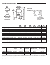
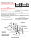
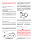
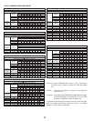
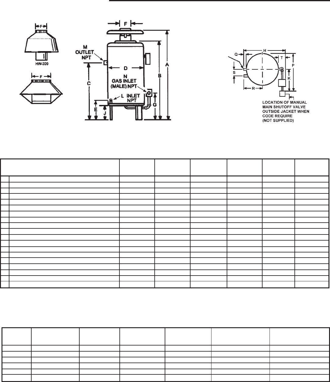
ROUGH-IN DIMENSIONS
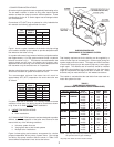
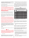
TABLE 2, SPECIFICATIONS - CANADIAN MODELS ONLY
Maximum
Maximum I.A.S. Maximum Max. Heat Transfer Max. Heat Transfer
Model Type of Gas BTUH(KW) BTUH(KW) Heat Loss Load Surface Area (Sq. Ft.) Surface Area (Sq. Ft.)
HWB-300 Natural & Propane 300,000 (88) 247,200 (72) 210,120 (62) 1,410 (.41) 1,051 (.31)
HWB-399 Natural & Propane 399,000 (116) 322,790 (95) 274,371 (80) 1,829 (.54) 1,372 (.40)
HWB-420 Natural & Propane 420,000 (123) 344,400 (101) 292,740 (86) 1.952 (57) 1,464 (.43)
HWB-520 Natural & Propane 520,000 (152) 429,000 (126) 364,650 (107) 2,431 (.71) 1,823 (.53)
HWB-610 Natural 610,000 (179) 502,600 (147) 427,210 (125) 2,848 (.83) 2,136 (.61)
HWB-610 Propane 610,000 (179) 488,000 (143) 414,800 (121) 2,765 (.81) 2,074 (.61)
Ratings shown are for current modern heating system design. Where A.O. Smith boilers are connected to heavy, cast iron radiator systems or where unusual pick-up or
large size piping conditions exist, reduce ratings by 10%.
NOTE: To compensate for the effects of high altitude areas above 2000 feet, the input, output and heating load ratings should be reduced
approximately 4% for each 1000 feet above sea level.
EXTRA OPENING
FOR THERMOMETER
AND RELIEF VALVE
HW/HWB-520, 610
AND HW--670
HW/HWB-610
AND HW-670
NATURAL GAS ONLY
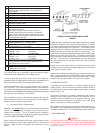
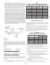
TABLE 1 MODELS
Prop. Nat.
HWB/ HWB/ HWB/ HWB/ HWB/ HWB/
HW-300 HW-399 HW-420 HW-520 HW-610/670 HW-610/670
A Overall height 65 (1651) 57-1/8 (1451) 57-1/8 (1451) 68-5/16 (1735) 67 (1702) 64-3/4 (1645)
B Height to top of jacket 43-1/4 (1099) 45-1/8 (1146) 45-1/8 (1146) 56-1/4 (1429) 56-1/4 (1429) 56-1/4 (1429)
C Floor to center line water inlet 36 (914) 38-3/4 (984) 38-3/4 (984) 46 (1168) 46 (1168) 46 (1168)
D Diameter of jacket 25-1/4 (641) 27 (686) 27 (686) 27 (686) 27 (686) 27 (686)
E Floor to center line water outlet 12 (305) 12 (305) 12 (305) 12 (305) 12 (305) 12 (305)
F Draft diverter outlet diameter 8 (203) 10 (254) 10 (254) 10 (254) 12 (305) 12 (305)
G Floor to center line gas inlet 16-1/2 (419) 16-3/4 (425) 16-3/4 (425) 18 (457) 18 (457) 18 (457)
H Overall depth 29-5/8 (753) 31-1/2 (800) 31-1/2 (800) 36-1/2 (927) 36-1/2 (927) 36-1/2 (927)
J Support height 9 (229) 9 (229) 9 (229) 9(229) 9 (229) 9 (229)
K Width of control string (approx.) 14 (356) 14 (356) 14 (356) 11(279) 11 (279) 11 (279)
L Pipe size of water inlet (NPT) 1-1/4 1-1/2 1-1/2 2 2 2
M Pipe size of water outlet(NPT) 1-1/4 1-1/2 1-1/2 2 2 2
N Pipe size of gas inlet (NPT) 3/4 1 1 1 1 1
P Control string plus 1/2 jacket dia. (approx.) 26-5/8 (676) 27-1/2(699) 27-1/2 (699) 24-1/2 (622) 24-1/2 (622) 24-1/2 (622)
Q Water outlet to jacket 1 (25) 1 (25) 1 (25) 3-1/2 (89) 3-1/2 (89) 3-1/2 (89)
R Water inlet casting to center line of jacket 10-1/8 (257) 11-1/4 (286) 11-1/4 (286) 12 (305) 12 (305) 12 (305)
S Horizontal length between water inlet and outlet 5-3/8 (137) 5-1/2 (140) 5-1/2 (140) 5-3/4 (146) 5-3/4 (146) 5-3/4 (146)
T Control string from jacket 5 (127) 5 (127) 5 (127) 7 (178) 7 (178) 7 (178)
Approx. shipping weight lbs. (Kilograms) 240 (109) 291 (132) 291 (132) 361 (164) 361 (164) 361 (164)
NOTE: All dimensions in inches (millimeters) except pipe size which is NPT.
DIMENSIONS IN INCHES