


4949
4949
49
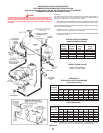
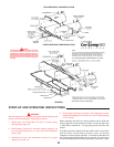
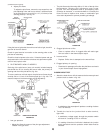
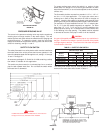
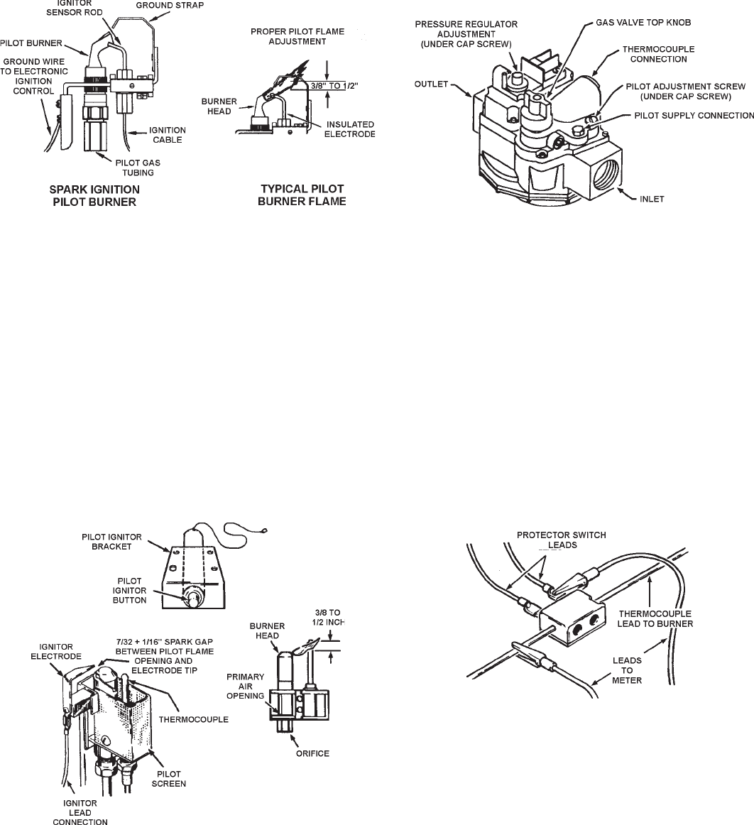
4. Adjust pilot flame.
To adjust the pilot flame, remove the cap screw from the
pilot adjusting valve and turn to deliver a sufficient flame
at the pilot burner to cover 3/8" to 1/2" (10-12mm) of the
sensing probe tip. See fig. 42.
FIGURE 42
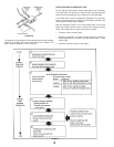
If the pilot burner ignites but the main burner fails to light, check for
gas flow to the main burner.
Check for good terminal connection at the sensing probe at the
pilot burner assembly.
Check for electrical power to the valve. If electrical power and gas
are present at the valve and the valve does not open when system
calls for heat, replace valve.
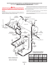
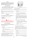
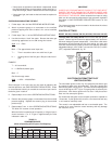
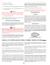
3. PILOT BURNER - NON-I.I.D. MODELS
Servicing of the pilot burner (every six months) includes keeping
pilot shield free of lint, cleaning the burner head, the primary air
opening and the orifice pilot burner, fig. 43a.
To ensure maximum millivolt output, the pilot burner flame should
envelop 3/8 to 1/2 inch of the thermocouple tip in fig. 43a. The
electrical output of the thermocouple will be affected by:
PIEZO PILOT IGNITOR
FIGURE 43A
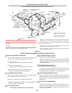
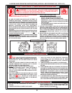
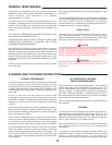
1. Low gas pressure
• Adjust pilot flame by means of the pilot gas adjustment
located in the gas valve.
• The pilot flame should envelop 3/8 to 1/2 inch of the tip of the
thermocouple. Remove pilot adjustment cover screw,
fig. 43b. Turn inner adjustment screw or pilot adjusting valve
clockwise to decrease, or counterclockwise to increase pilot
flame. Be sure to replace cover screw on combination gas
valve after adjustment to prevent possible gas leakage.
FIGURE 43B
2. Clogged pilot burner orifice.
• Clean or replace orifice. A clogged orifice will restrict gas
flow and result in low thermocouple output.
3. Incorrect orifice.
• Replace. Orifice size is stamped on the wrench flats.
4. Clogged primary air opening.
• Restricted air passages will soften the pilot flame and result
in poor thermocouple flame impingement.
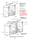
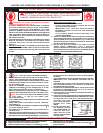
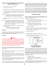
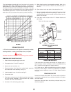
CLOSED CIRCUIT TEST
1. Attach the leads from a millivolt meter to the thermocouple and
junction block as shown in fig. 43c.
FIGURE 43C
• A satisfactory thermocouple will produce a reading of above
14 to 18 millivolts.
2. Transfer the lead on the junction block to other terminal,
figure 43d.
• A satisfactory voltage supply through the protector switch
will result in a reading of 8 to 14 millivolts.
• If a reading of less than 8 millivolts is obtained, the junction
block connections and the protector switch leads must be
checked.
(Continued from Page 46)