


1111
1111
11
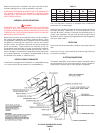
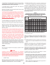
• In table 6, select the row showing the distance to the most
remote outlet or the next longer distance if the table does not
give the exact length. This is the only distance used in
determining the size of any section of gas piping. If the gravity
factor is to be applied, the values in the selected row of table 6
are multiplied by the appropriate multiplier from table 7.
• Total the gas demands of all appliances on the piping system.
Enter table 6, on the left hand side, at the row equal to or just
exceeding the distance to the most remote outlet. Select the
pipe size in the row with a capacity equal to or just exceeding
the total gas demand. This is the required main gas supply
line size leading away from the gas meter or regulator. To
determine the pipe size required for each branch outlet leading
away from the main supply line, determine the gas demand for
that outlet. Enter table 6 on the same row, and select the branch
pipe size for a capacity equal to or just exceeding the demand
at that outlet. The main line can be resized for a lesser capacity
after each branch outlet, since the gas demand is reduced.
Total the gas demands of all remaining appliances branching
off downstream on the main gas line. Re-enter table 6 in the
same row and select the appropriate pipe size with adequate
capacity. Repeat the branch sizing and main line re-sizing for
any remaining appliances in the system.
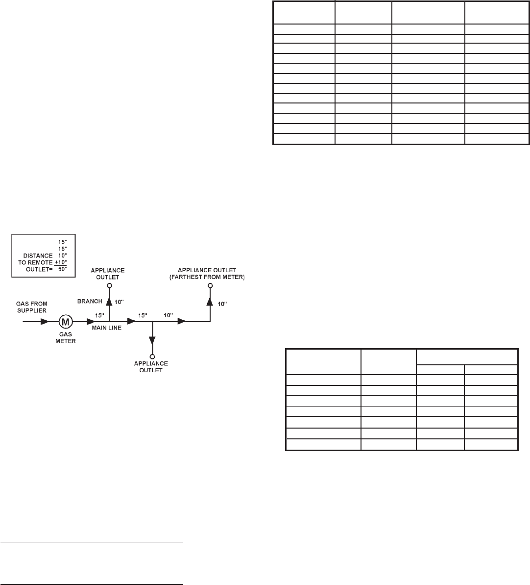
EXAMPLE
Job Condition:
Determining the required gas pipe size for a system composed of
two HWB/HW-420 boilers and two HWB/HW-610 boilers to be
installed as a multiple group, 50 lineal feet from meter. Gas to be
used has a .60 specific gravity and heating value of 1,000 Btu per
cubic foot.
Solution:
2 HWB/HW-420 Boilers = 840,000 Btuh
2 HWB/HW-610 Boilers = 1,220,000 Btuh
Total Btuh Input = 2,060,000 Btuh
Total Btuh Input = 2,060,000 Btuh = 2,060 cf/h
Btu per Cubic Foot of Gas 1,000
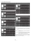
With a cubic foot per hour demand of 2,060 and with 50 lineal feet
of gas supply line, table 6 shows a pipe size of 3" (76mm) is
required.
NOTE: For other than .60 specific gravity, apply multiplier factor
as shown in table 7.
TABLE 7
MULTIPLIERS TO BE USED WITH TABLE 6 WHEN APPLYING
THE GRAVITY FACTOR TO OTHER THAN .60 SPECIFIC GRAVITY
Specific Specific
Gravity Multiplier Gravity Multiplier
.35 1.31 1.00 .78
.40 1.23 1.10 .74
.45 1.16 1.20 .71
.50 1.10 1.30 .68
.55 1.04 1.40 .66
*.60 (Nat.) 1.00 *1.50 (Prop.) .63
.65 .96 1.60 .61
.70 .93 1.70 .59
.75 .90 1.80 .58
.80 .87 1.90 .56
.85 .84 *2.00 (Butane) .55
.90 .82 2.10 .54
*Use these correction factors if exact specific gravity of the gas is not
known.
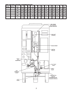
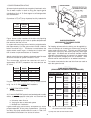
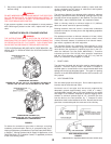
GAS PRESSURE REGULATORS
The gas pressure regulator is included in the combination gas
valve, fig. 6, and is set to operate on the gas specified on the boiler
model and rating plate.
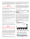
Periodically check main burner, fig. 41, and pilot flame, fig. 42, for
proper operation. This should be checked every six months.
Do not subject the gas valve to inlet gas pressures of more than
14" W.C. (1/2 P.S.I.). If higher gas pressures are encountered, a
service regulator is necessary.
TABLE 8
CORRECT MANIFOLD PRESSURE FOR FULL
BOILER INPUT (IN INCHES OF WATER COLUMN)
Model Rated Manifold Pressure
Number Input Natural Propane
HWB/HW-300 300,000 3.5 10.0
HWB/HW-399 399,000 3.2 9.5
HWB/HW-420 420,000 3.5 10.0
HWB/HW-520 520,000 3.5 10.0
HWB/HW-610 610,000 3.5 10.0
HW-670 Nat. 660,000 3.5
HW-670 Prop. 670,000 10.0
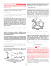
Adjustment, if required, is performed as follows:
1. Set primary system temperature control dial (thermostat) at
lowest setting so that boiler will not call for heat.
2. Attach a pressure gauge to the tapping in the control string
elbow.
3. Reset primary system temperature control dial (thermostat)
to highest setting. Main burner will now ignite.
4. With main burner firing, adjust pressure, if necessary, by turning
pressure regulator adjusting screw with a screwdriver.
• Clockwise to increase pressure.
• Counterclockwise to decrease pressure.
5. Set primary system temperature control dial (thermostat) to
lowest setting.
6. Remove pressure gauge and replace sealing plug.