


5353
5353
53
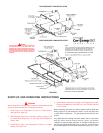
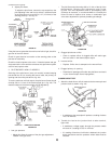
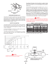
PROTECTOR SWITCH
FIGURE 48
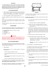
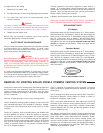
PRESSURE REDUCING VALVE
The screen in the pressure reducing valve may require occasional
cleaning due to foreign material in the water supply. This will
restrict the flow and could reduce the effectiveness of purging and
prolong filling time. To inspect the screen, close the main water
supply valve ahead of the pressure reducing valve and remove the
screen for cleaning, see fig’s. 1 and 2.
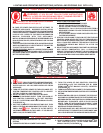
SAFETY FLOW SWITCH
The safety flow switch is a safety device which must be installed at
the water outlet of the unit to prevent main burner operation in the
event of inadequate water flow through the unit, see fig’s. 10 through
12 and 17 through 27.
An accessory package A. O. Smith No. 211480 containing a safety
flow switch is available for this application.
This switch may be mounted in a horizontal pipe line or a vertical
pipe line with upward water flow. Do not install the switch where
the water flow is downward.
For proper performance mount the switch in a section of pipe
where there is a straight run of at least 5 pipe diameters on each
side of the flow switch (i.e. do not locate adjacent to valves, elbows,
orifices, etc.).
The flow switch shall be mounted in a standard 1-1/2" x 1-1/2" x 1"
tee for a 1-1/2" pipe application. For larger pipe sizes use a
reducing tee in order to keep the switch as close to the pipe as
possible. Install the flow switch in the branch (top) opening of the
reducing tee and provide adequate paddle length in the flow stream.
For example in a 2" pipe installation use a 2" x 2" x 1" reducing tee.
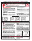
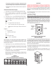
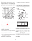
For 2", or 3" pipe use paddle segments as supplied. For other
pipe sizes (i.e. 1-1/4", 1-1/2" and 2-1/2") trim the paddle to the
proper pipe size, see fig. 49. If a standard tee is used, install a face
or hex bushing in the top opening. The paddle must be adjusted
or trimmed to the size of the pipe in which it will be installed.
CAUTION
Any part of the paddle must not touch the pipe or any restrictions in
the pipe. Screw the flow switch in position so the flat of the paddle
is at right angles to the flow. The arrow on the side case must point
in the direction of the flow.
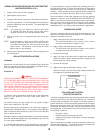
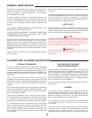
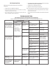
TABLE 11 - SAFETY FLOW SWITCH
Minimum Pipe Rate
Contacts Closed Contacts Open
Model (Flow) (No Flow)
Number GPM LPS GPM LPS
HWB/HW-300 5.8 0.36 3.7 0.23
HWB/HW-399 7.5 0.47 5.0 0.31
HWB/HW-420 7.5 0.47 5.0 0.31
HWB/HW-520 13.7 0.86 9.5 0.60
HWB/HW-610/670 13.7 0.86 9.5 0.60
The safety flow switch may be field adjusted to obtain higher
minimum flow rates than those shown in table 11.
CAUTION
Paddle must be trimmed at the dotted arc. It must not touch
the pipe or have any restriction when installed
FIGURE 49