


5
FEATURES
IMPORTANT
Only qualified personnel shall perform the initial firing of the heater.
At this time the user should not hesitate to ask the individual any
questions regarding the operation and maintenance of the unit.
Lighting and Operating instructions are included at the rear of this
manual. By using this checklist the user may be able to make
minor operational adjustments and save unnecessary service calls.
However, the user should not attempt repairs which are not listed
under the USER column.
SAFETY RELIEF VALVES
Your local code authority may have other specific relief valve
requirements not covered below.
WARNING
THE PURPOSE OF A SAFETY RELIEF VALVE IS TO AVOID
EXCESSIVE PRESSURE WHICH MAY CAUSE TANK
EXPLOSION, SYSTEM OR BOILER DAMAGE.
TO AVOID WATER DAMAGE A DRAIN LINE MUST BE
CONNECTED TO A SAFETY RELIEF VALVE TO DIRECT
DISCHARGE TO A SAFE LOCATION. A DRAIN LINE MUST NOT
BE REDUCED FROM THE SIZE OF THE VALVE OUTLET AND IT
MUST NOT CONTAIN ANY VALVES BETWEEN THE BOILER AND
THE RELIEF VALVE OR THE RELIEF VALVE AND THE DRAIN
EXIT. IN ADDITION, THERE SHOULD NOT BE ANY
RESTRICTIONS IN A DRAIN LINE NOR SHOULD IT BE ROUTED
THROUGH AREAS WHERE FREEZING CONDITIONS MIGHT
OCCUR. DO NOT THREAD OR CAP THE DRAIN LINE EXIT.
RESTRICTING OR BLOCKING A DRAIN LINE WILL DEFEAT THE
PURPOSE OF THE RELIEF VALVE AND MAY CREATE AN
UNSAFE CONDITION. INSTALL A DRAIN LINE WITH A
DOWNWARD SLOPE SUCH THAT IT NATURALLY DRAINS
ITSELF.
If any safety relief valve is replaced, the replacement valve must
comply with the latest version of the ASME Boiler and Pressure
Vessel Code, Section IV (“HEATING BOILERS”). Select a relief
valve with a discharge rating NOT less than the boiler input, and a
set pressure NOT exceeding the working pressure of any component
in the system.
An ASME rated temperature and pressure relief valve must be
installed on each and every water storage tank in a hot water supply
system.
The storage tank temperature and pressure relief valve must comply
with the applicable construction provisions of the Standard for Relief
Valves and Automatic Gas Shutoff Devices for Hot Water Supply
Systems, ANSI Z21 or CAN/CSA-B149.1 (latest edition). The valve
must be of the automatic reset type and not embody a single-use
type fusible plug, cartridge or linkage.
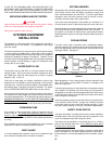
ELECTRONIC INTERMITTENT PILOT
IGNITION CONTROL
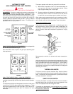
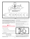
ALL MODELS - The solid state ignition control, fig. 2, ignites the
pilot burner gas by creating a spark at the pilot assembly. Pilot gas
is ignited and burns during each running cycle. The main burner
and pilot gases are cut off during the “OFF” cycle. Pilot gas ignition
is proven by the pilot sensor. Main burner ignition will not occur if
the pilot sensor does not first sense pilot ignition.
FIGURE 2
On natural gas models the igniter control continues to operate
(creating a spark) until the pilot burner is ignited or the ignition
system shuts down. Shut down occurs automatically if the pilot
burner does not ignite within 15 seconds. The unit then waits for
(5) minutes and retries ignition (standard models).
The electronic intermittent pilot ignition control and the 100% lockout
control are non-adjustable devices.
(See troubleshooting steps on page 40). If pilot is not lit and sensed
within the flame establishing timing for each module, the appliance
will shut down.
MANUAL RESET HIGH TEMPERATURE
SAFETY LIMIT CONTROL
This device senses water temperature in the boiler. When water
temperature exceeds dial setting, power to main gas valve is
interrupted and the boiler is shut down.
HOT WATER SUPPLY - Manual reset - factory set at 210°F (100°C).
Water temperature must drop at least 20°F (11°C) before reset is
possible.
HYDRONIC HEATING - Manual reset - factory set at 250°F (121°C).
Water temperature must drop at least 20°F (11°C) before reset is
possible.
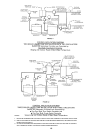
Single stage and modulating units use a combined control as shown
in fig. 4.
Dual stage models are equipped with a limit like one shown in
figure 3.