


40
The time between cleaning will vary from two to six months
depending upon water conditions and usage. A change of
approximately 5°F in the normal temperature rise through the boiler
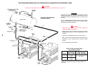
is usually an indication that scale should be removed. For long
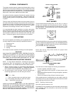
life, copper or brass is recommended for all valves, pipe and fittings
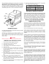
used between gate valves “A” and “B” and the boiler, see fig. 29.
DELIMING SOLVENTS
A. O. Smith recommends the use of UN•LIME for deliming. UN•LIME
is a patented food grade acid.
UN
•LIME may be obtained from your dealer, distributor or the
A.O. Smith Water Products Company, Part No. 4763 (1 gal. [4 L])
packed 4 gallons (16 L) per case, Part No. 4813 (5 gal. [20 L])
single container.
CAUTION
Read the instructions on the label of the UN
•LIME container.
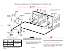
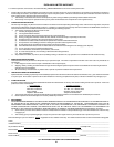
REMOVING LIGHT DEPOSITS OF SCALE
1. Shut off electric and gas supply to the burner.
2. Close gate valves "A" and "B", see fig. 29.
3. Open drain cock and drain unit.
4. Install standpipe in tee of inlet/outlet line, see fig. 29.
5. Close drain cock.
6. Slowly pour required amount of UN•LIME shown in table below
into unit through standpipe. Direct solution into suitable
container with hose.
7. Continue to fill until foaming action stops. For heavy deposits
pour through twice.
8. When foaming action has stopped completely, allow 10 to 15
minutes for UN•LIME to dissolve any remaining scale in the
unit.
9. Open the drain cock and drain all UN•LIME from unit.
10. Remove 12" standpipe and install plug fitting. Close drain
cock. Open valve "A" allowing fresh water to flow through unit
and drain out hose for 5 minutes.
11. Close valve "A", open drain cock, remove standpipe and hose
assembly and install plug fitting.
12. Close drain cock and open valves "A" and "B". Purge system
of air. Restore electric and gas supply.
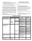
AMOUNT OF UN
•LIME REQUIRED
720, 840, 960, 1080 3 gallons (12 L)
1210, 1350 4 gallons (16 L)
1480, 1610, 1810 6 gallons (24 L)
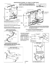
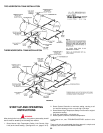
MECHANICAL REMOVAL OF DEPOSITS
To service heat exchanger tubes remove cover panel from far side
of water connections. This will expose the heat exchanger return
bends. Return bends may be removed using a standard 9/16"
deep socket ratchet exposing the tube ends. Inspect to ensure
tubes are free of scale and deposits. If scaled, remove deposits
with a stiff wire brush or mechanical tube cleaner to bare metal.
Install new "O" rings and install return bends. Flush system.
REMOVAL OF AN EXISTING BOILER FROM A
COMMON VENTING SYSTEM
At the time of removal of an existing boiler, the following steps
shall be followed with each appliance remaining connected to the
common existing system placed in operation, while the other
appliances remaining connected to the common venting system
are not in operation.
Seal any unused openings in the common venting system.
Visually inspect the venting system for proper size and horizontal
pitch and determine there is no blockage or restriction, leakage,
corrosion and other deficiencies which could cause an unsafe
condition.
Insofar as is practical, close all building doors and windows and all
doors between the space in which the appliance remaining
connected to the common venting system are located and other
spaces of the building. Turn on clothes dryers and any appliance
not connected to the common venting system. Turn on any exhaust
fans, such as range hoods and bathroom exhausts, so they will
operate at maximum speed. Do not operate a summer exhaust
fan. Close fireplace dampers.
Place in operation the appliance being inspected. Follow the lighting
instructions. Adjust thermostat so appliance will operate
continuously.
Test for spillage at the draft hood relief opening after 5 minutes of
main burner operation. Use the flame of a match or candle, or
smoke from a cigarette, cigar or pipe.
After it has been determined that each appliance remaining
connected to the common venting system properly vents when
tested as outlined above, return doors, windows, exhaust fans,
fireplace dampers and any other gas-burning appliance to their
previous condition of use.
Any improper operation of the common venting system should be
corrected so the installation conforms with the National Fuel Gas
Code, ANSI Z223.1 and/or CAN/CSA B149, Installation Codes.
When resizing any portion of the common venting system, the
common venting system, the common venting system should be
resized to approach the minimum size as determined using the
appropriate tables in Appendix F in the National Fuel Gas Code,
ANSI Z223.1 and/or CAN/CSA B149 Installation Codes.