


35
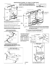
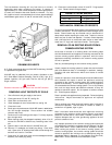
1. Remove main burners from unit.
2. Check that burner venturi and ports are free of foreign matter.
3. Clean burners with bristle brush and/or vacuum cleaner 3/4"
DO NOT distort burner ports or pilot location.
4. Reinstall burners in unit. Making sure front and rear of burners
are installed correctly in burner support brackets.
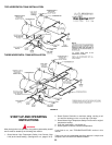
Also check for good flow of combustion and ventilating air to the
unit. Maintain a clear area around the boiler at all times.
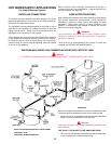
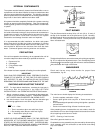
After placing the boiler in operation check the ignition system safety
shutoff devices for proper operation. To accomplish this with the
main burners operating, close the pilot adjusting valve on the left
side of the manifold. Within four seconds the main burners and
pilot should extinguish and the spark igniter on the pilot assembly
should begin sparking. If this does not occur immediately,
discontinue gas supply by closing main manual shutoff and call a
qualified serviceman to correct the situation. If the burners
extinguish, and pilot assembly begins sparking, the system is
operating correctly so discontinue electrical power, open pilot
adjusting valve, and light boiler in accordance with lighting and
operating instructions.
For installations above 2000 feet (600 m), refer to HIGH ALTITUDE
INSTALLATIONS in the installation section.
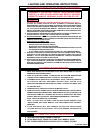
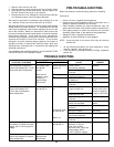
PRE-TROUBLE-SHOOTING
Before any extensive trouble-shooting, perform the following:
Ensure that:
— Power (120 vac) is supplied to the appliance.
— System control (tank temperature control, thermostat, etc.) is
calling for appliance operation (call for heat).
— Other contacts (switches) are closed (transformer relay, low
water cutoff, flow switch, limit controls, pressure switches, etc.)
— Gas supply pressure is within the maximum and minimum
operating ranges listed on the appliance rating plate/label.
— Voltage (24 vac) is supplied by transformer.
— Appliance is wired according to wiring diagram.
NOTE: Cross wiring the 24 volt circuit of the relay will short the
transformer.
— All wire terminals/connectors are firmly attached to valves,
modules, switches, limit controls, etc.
— There has been no damage caused by freezing, inoperative
pumps, etc.
SYSTEM OPERATION
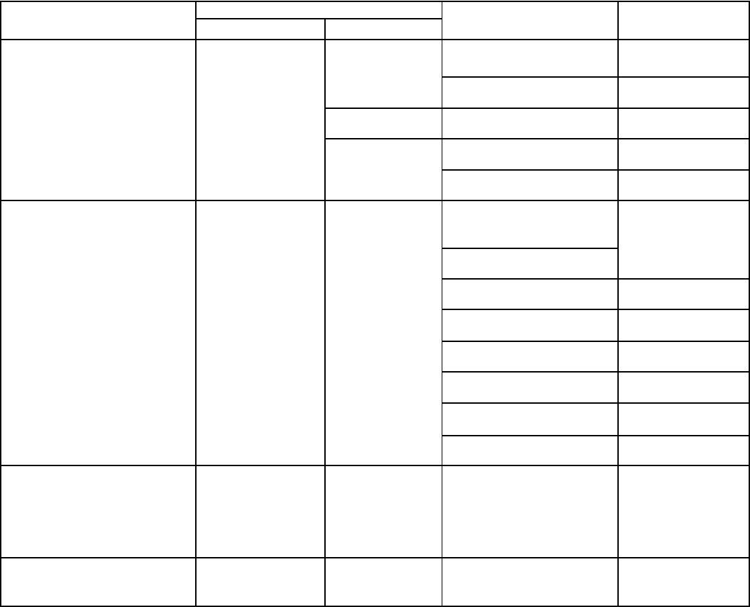
CHECKOUT SEQUENCE CORRECT INCORRECT CAUSE REMEDY
Set tank/system temperature Circulating pump Pump and burner Temp. control Replace.
control (thermostat) 20°F (12°C) and burner remain on. (thermostat) defective.
below tank water temperature. shutoff. System wiring Correct wiring.
incorrect
With thermal Circulating pump Pump wired for Correct wiring.
balancer, pump on. continuous operation.
off delay of Burner on. Gas valve stuck Correct or replace
approximately or defective. valve.
two minutes. System wiring is Correct wiring.
incorrect.
Set tank/system temperature Circulating pump Circulating pump Auto reset high limit Replace. (If problem
control (thermostat) 20°F and burner on. on. control set too low. proven to be at this
(12°C) above tank/system control by applying
water temperature. Auto reset high limit control jumper to terminals).
differential too wide.
System wiring is Correct wiring.
incorrect.
Manual reset high limit Depress reset
switch has activated. button.
Gas valve or wiring
defective.
Circulating pump Power off or system Check power supply
and burner off. wiring is incorrect. and wiring.
Temp. control Replace.
(thermostat) defective.
Burner on. System wiring is Correct wiring.
incorrect.
Boiler outlet temperature Circulating pump. Circulating pump Auto reset high limit control Replace.
exceeds 210°F (98°C) hot water and burner on. defective, or set too
supply, 250°F (120°C) hydronic high (max. should
supply. be set at 200°F [93°C] hot
water supply, 240°F
[115°C] hydronic supply).
Set tank/system temperature System maintains
control (thermostat) for desired desired water
water temperature. temperature.
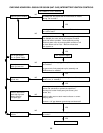
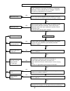
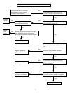
TROUBLE-SHOOTING