


2
FOREWORD
CAUTION
TEXT PRINTED OR OUTLINED IN RED CONTAINS
INFORMATION RELATIVE TO YOUR SAFETY. PLEASE READ
THOROUGHLY BEFORE USING APPLIANCE.
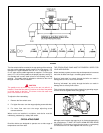
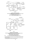
Detailed installation diagrams are in this manual. These diagrams
will serve to provide the installer with a reference for the materials
and method of piping suggested. IT IS NECESSARY THAT ALL
WATER AND GAS PIPING AND THE ELECTRICAL WIRING BE
INSTALLED AND CONNECTED AS SHOWN IN THE DIAGRAMS.
CHECK THE DIAGRAMS THOROUGHLY BEFORE STARTING
INSTALLATION TO AVOID POSSIBLE ERRORS AND TO
MINIMIZE TIME AND MATERIALS COST.
This design complies with the latest edition of the
ANSI Z21.13
CSA 4.9 low-pressure boiler.
Particular attention should be given to the installation of
thermometers at the locations indicated in the diagrams as these
are necessary for checking the operation of the boiler.
MAKE SURE THE GAS ON WHICH THE BOILER WILL OPERATE
IS THE SAME AS THAT SPECIFIED ON THE UNIT RATING PLATE.
The boiler installation must conform to these instructions and the
requirements of the local authority having jurisdiction.
Where required by the authority having jurisdiction, the installation
must conform to the Standard for Controls and Safety Devices for
Automatically Fired Boilers, ANSI/ASME CSD-1.
In the absence of local code requirements, the boiler installation
must conform to the most current
National Fuel Gas Code, ANSI
Z223.1 and/or CAN/CSA-B149.1-00 installation codes.
These manuals can be purchased from the CSA International,
8501 East Pleasant Valley Road, Cleveland, OH 44131 or 178
Rexdale Boulevard, Toronto, Ontario Canada, M9W 1R3.
REPLACEMENT PARTS
Replacement parts may be ordered through A. O. Smith dealers,
authorized servicers or distributors. Refer to the Yellow Pages for
where to call or contact (in United States) the A.O. Smith Water
Products Company, 5621 West 115th Street, Alsip, IL 60803,
1-800-433-2545 or (in Canada) A.O. Smith Enterprises Ltd., 768
Erie Street, Stratford, Ontario, Canada N5A 6T3, 800-265-8520.
When ordering parts be sure to state the quantity, part number and
description of the item including the complete model and serial
number as it appears on the product. Refer to the parts lists for
more information.
For Technical Assistance call A.O. Smith Technical Information
Center at 1-800-527-1953.
WARNING
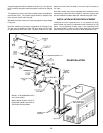
THE INLET/OUTLET WATER MANIFOLD ON YOUR A. O. SMITH
UNIT INCORPORATES AN “O RING" WATER SEAL ASSEMBLY.
THE MANIFOLD IS NOT DESIGNED TO SUPPORT THE WEIGHT
OF THE WATER PIPING SYSTEM. AS ON ALL BOILER
INSTALLATIONS, SPECIAL CARE MUST BE TAKEN TO ENSURE
PROPER SUPPORT.
WARNING
UNDER NO CIRCUMSTANCES SHOULD THE EQUIPMENT
ROOM WHERE THE BOILER IS INSTALLED EVER BE UNDER
NEGATIVE PRESSURE. PARTICULAR CARE MUST BE TAKEN
WHEN EXHAUST FANS, COMPRESSORS, AIR HANDLING
EQUIPMENT, ETC., MAY INTERFERE WITH THE COMBUSTION
AND VENTILATION AIR SUPPLIES OF THIS BOILER.
Page
FOREWORD................................................................................ 2
REPLACEMENT PARTS .............................................................. 2-3
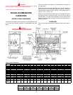
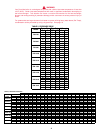
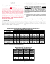
ROUGH-IN DIMENSIONS/CAPACITIES ...................................... 3-4
Installation Clearances .............................................................. 3
Levelling ................................................................................... 3
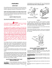
FEATURES................................................................................... 5
Safety Relief Valves .................................................................. 5
Electronic Intermittent PIlot Ignition Control .............................. 5
Manual Reset High Temperature Safety Limit Control ............... 5
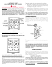
Automatic Reset High Temperature Control .............................. 6
Thermal Balancer ..................................................................... 6
Safety Flow Switch ................................................................... 6
INSTALLATION INSTRUCTIONS ................................................. 7
Required Ability ........................................................................ 7
Location ................................................................................... 7
Air Requirements ..................................................................... 7-8
Venting the Boiler ..................................................................... 8-9
Gas Connections...................................................................... 9
Purging .................................................................................... 10-11
High Altitude Installations ......................................................... 11
Wiring Connections .................................................................. 11-12
Servicing Wiring And/Or Control .............................................. 12
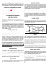
SYSTEM EQUIPMENT INSTALLATION ....................................... 12
Water Supply Line .................................................................... 12
Expansion Tank ........................................................................ 12
Vent Valves .............................................................................. 12
System Headers ...................................................................... 12
Cooling Piping .......................................................................... 12
Safety Flow Switch ................................................................... 12-13
Circulating Pump...................................................................... 13-14
Low Water Cutoff ..................................................................... 14
Tank Temperature Control ........................................................ 14
SYSTEM INSTALLATION ............................................................. 14
Conventional Space Heating Installation ................................... 14-15
Installation As Boiler Replacement ............................................ 15-17
Linear-Temp Space Heating Applications .................................. 17
Linear-Temp Space Heating Installations .................................. 17-20
Wiring and Schematic Diagrams .............................................. 21-26
HOT WATER SUPPLY APPLICATIONS ....................................... 27-32
Water Line Connections ........................................................... 27
Hard Water Conditions ............................................................. 27
START-UP AND OPERATING INSTRUCTIONS .......................... 32
LIGHTING AND OPERATING INSTRUCTIONS ........................... 33
Internal Contaminants .............................................................. 34
Precautions .............................................................................. 34
Checking and Adjusting the Input ............................................. 34
Pilot Burner .............................................................................. 34
Main Burner ............................................................................. 34-35
PRE-TROUBLESHOOTING ......................................................... 35
TROUBLESHOOTING.................................................................. 35-38
GENERAL MAINTENANCE .......................................................... 39
Relief Valve .............................................................................. 39
Venting Maintenance ................................................................ 39
Heat Exchanger Preventive Maintenance.................................. 39
Deliming ................................................................................... 39-40
Deliming Solvents..................................................................... 40
Removing Light Deposits of Scale ............................................ 40
Removal of an Existing Boiler From A Common Venting
System ................................................................................ 40
LIMITED WARRANTY .................................................................. 41
CONTENTS
Page