


18
generator type boilers establish temperature rises. The deciding
factor in choice of boiler temperature rise relates to the boiler inlet
temperature. Boiler outlet, minus system temperature drop, is
boiler inlet temperature. THE BOILER TEMPERATURE RISE
SHOULD NOT RAISE THE OUTLET TEMPERATURE UP TO THE
MAXIMUM 250°F (115°C) SETTING OF THE LIMIT CONTROL.
If inlet temperature (plus temperature rise) of any boiler on the
group exceeds 240°F (115°C), that boiler and all downstream
boilers will shut down (cycle on and off).
B. Commercial Boiler Replacements
Application of LINEAR-TEMP to a commercial boiler replacement
with an old multiple pump installation is an excellent way to
modernize the system. The A. O. Smith boiler(s) should be
installed on a pipe loop with a separate circulating pump. Use
table 7 to determine pipe sizes and operating ranges.
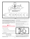
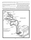
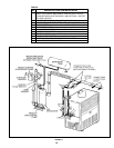
The following illustration shows how the system headers should
be connected to pipe loop that is installed with the replacement
boiler(s). Make-up water connections, and accessories are not
shown.
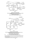
Supply and return headers of the old system should be connected
to the boiler loop with a pair of tees set close together. The boiler
loop pump and the boiler(s) should be wired to operate only when
any of the system pumps are in operation. The number of zone
pumps that may be in operation at any particular time will take
their required flow rate out from the first tee in the boiler piping.
This water will be circulated through the proper branches from the
supply header to the zones calling for heat. The water will be brought
back to the return header and then into the second tee in the boiler
pipe loop. There will be no conflict between the boiler pump and
the zone pumps when the two tees in the boiler loop are placed
close together.
Normal use of flow control valves is required to prevent cross
circulation of zones as with any multiple pump system.
Large systems with multiple boilers should include main water
temperature controls (with or without outdoor reset) to sequence
the boiler on and off, in relation to the load on the system.
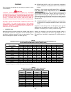
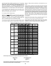
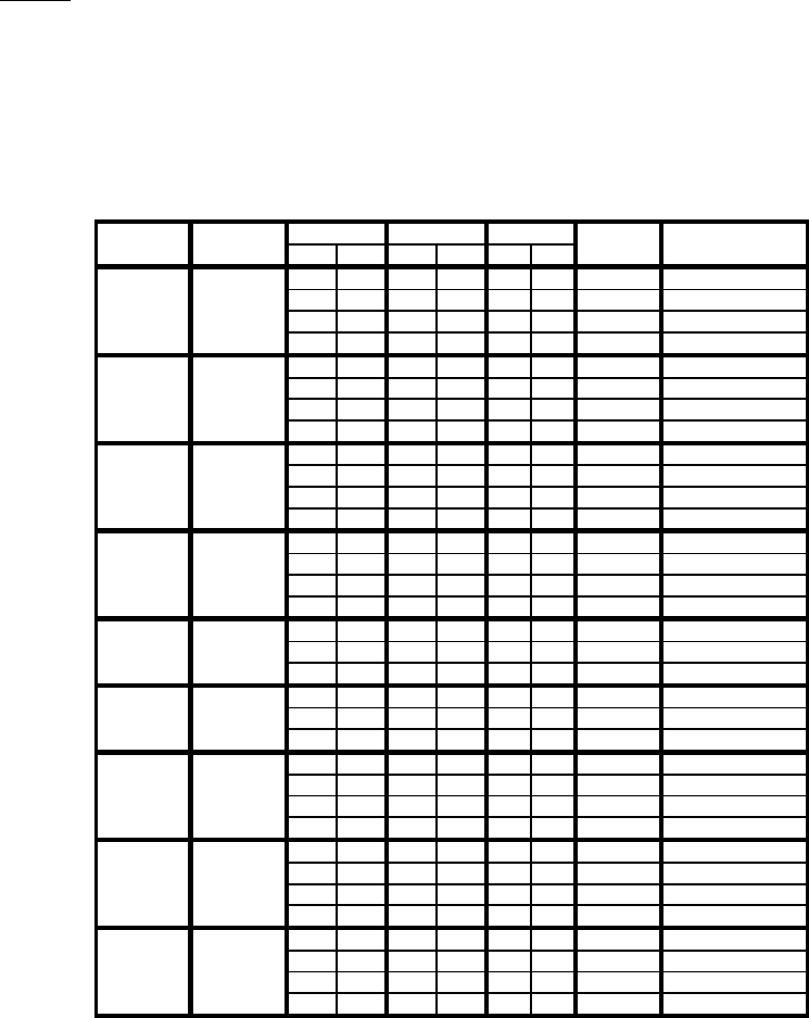
Pressure drop includes the loss through 40' (12 m) of pipe and normal fittings.
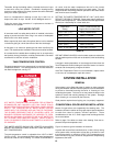
Water Category Grain Hardness per Gal.
Soft 1 through 7.5
Normal 7.6 through 17
Hard Over 17
Taco pumps shown. Equivalent Armstrong, Bell & Gossett or Grundfos acceptable.
Always ensure adequate support for pump and piping.
TABLE 7, DuraMax Pump Performance Requirements
Water
Pipe Size Taco Circulator
Category
FC
GPM LPM ft
M Sched. 40 Models
Soft
35 19.4 34 127 3.7 1.1 2" #0012 (1/7 HP)
Normal
25 13.9 47 178 6.2 1.9 2" #120 (1/6 HP)
Hard
18 10.0 65 248 12.6 3.8 2" #1935 (1/3 HP)
Hard
18 10.0 65 248 7.4 2.3 2 1/2" #121 (1/4 HP)
Soft
35 19.4 39 149 5.9 1.8 2" #0012 (1/7 HP)
Normal
25 13.9 55 208 8.9 2.7 2" #120 (1/6 HP)
Hard
18 10.0 76 289 15.1 4.6 2" #1935 (1/3 HP)
Hard
18 10.0 76 289 10.2 3.1 2 1/2" #1935 (1/3 HP)
Soft
35 19.4 45 170 6.6 2.0 2" #0012 (1/7 HP)
Normal
25 13.9 63 238 12.1 3.7 2" #1935 (1/3 HP)
Normal
25 13.9 63 238 7.6 2.3 2 1/2" #121 (1/4 HP)
Hard
18 10.0 87 330 12.9 3.9 2 1/2" #1935 (1/2 HP)
Soft
35 19.4 51 193 7.0 2.1 2" #120 (1/6 HP)
Normal
25 13.9 72 271 13.1 4.0 2" #1935 (1/3 HP)
Normal
25 13.9 72 271 7.1 2.2 2 1/2" #121 (1/4 HP)
Hard
19 10.6 94 356 11.3 3.4 2 1/2" #1935 (1/2 HP)
Soft
35 19.4 57 217 4.7 1.4 2 1/2" #120 (1/6 HP)
Normal
25 13.9 80 303 8.8 2.7 2 1/2" #121 (1/4 HP)
Hard
19 10.6 105 399 13.4 4.1 2 1/2" #1935 (1/2 HP)
Soft
35 19.4 64 242 6.0 1.8 2 1/2" #121 (1/4 HP)
Normal
25 13.9 89 339 10.5 3.2 2 1/2" #1935 (1/3 HP)
Hard
18 10.0 124 470 18.9 5.8 2 1/2" #1935 (3/4 HP)
Soft
35 19.4 68 259 6.3 1.9 2 1/2" #121 (1/4 HP)
Normal
25 13.9 96 362 12.7 3.9 2 1/2" #1935 (1/2 HP)
Hard
18 10.0 133 503 20.5 6.2 2 1/2" #1935 (3/4 HP)
Hard
18 10.0 133 503 12.2 3.7 3" #133 (3/4 HP)
Soft
35 19.4 74 281 8.0 2.4 2 1/2" #121 (1/4 HP)
Normal
25 13.9 104 394 13.6 4.1 2 1/2" #1935 (1/2 HP)
Hard
20 11.1 130 492 20.7 6.3 2 1/2" #1935 (3/4 HP)
Hard
20 11.1 130 492 12.4 3.8 3" #133 (3/4 HP)
Soft
38 21.1 77 291 8.2 2.5 2 1/2" #121 (1/4 HP)
Normal
28 15.6 104 395 13.8 4.2 2 1/2" #1935 (1/2 HP)
Hard
22 12.2 133 503 20.9 6.4 2 1/2" #1935 (3/4 HP)
Hard
22 12.2 133 503 12.6 3.8 3" #133 (3/4 HP)
* - Head loss includes the loss through 40 feet (12 m) of pipe and normal fittings.
Model
Temp Rise
Flow Rate HdLoss*
DW-720
DW-840
DW-960
DW-1080
DW-1810
DW-1210
DW-1350
DW-1480
DW-1610