


13
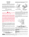
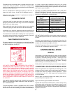
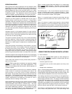
The flow switch shall be mounted in the top opening of the reducing
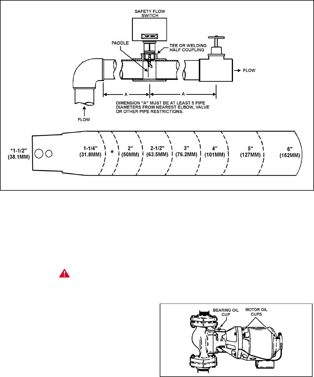
tee and provide adequate paddle length in the flow stream. For
example in a 2" pipe installation use a 2" x 2" x 1" reducing tee. For
2" or 3" pipe use the paddle segments as supplied. For other pipe
sizes (i.e. 2-1/2") trim the paddle to the proper pipe size, see fig. 8.
If a standard tee is used, install a face or hex bushing in the top
opening. The paddle must be adjusted or trimmed to the size of
the pipe in which it will be installed.
CAUTION
The paddle must not touch any part of the tee into which it is
installed. Screw the flow switch in position so the flat of the paddle
is at right angles to the flow. The arrow on the side case must
point in the direction of the flow.
To adjust the flow rate setting:
1. Remove the flow switch cover.
2. For higher flow rate—turn the range adjusting screw clockwise.
3. For lower flow rate—turn the range adjusting screw
counterclockwise.
Where units are installed in multiples, each boiler must be
individually protected by a safety flow switch.
CIRCULATING PUMP
Dura-Max boilers are designed to operate over a wide range of
temperatures and flow rates.
THE CIRCULATING PUMP MUST BE PROPERLY SIZED FOR
YOUR APPLICATION.
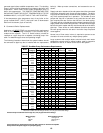
Water hardness, system pressure drop and temperature rise across
the boiler all affect how large a circulating pump must be.
Running "hard water" too slowly through the boiler can result in
damage due to lime or scale accumulation.
Running "soft water" too quickly through the boiler can result in
damage due to velocity flow erosion.
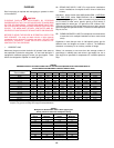
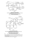
Table 4 has been designed to assist in determining operating ranges.
Use this chart as a guide when sizing pumps.
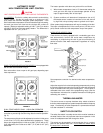
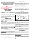
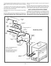
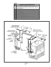
FIGURE 9
Although each circulator that requires oil is oiled and operated by
the manufacturer, IT MUST BE OILED AGAIN BEFORE BEING
OPERATED. Oil the three oil cups (2 on the motor, 1 on the pump)
as instructed on the oil tube supplied with the unit, fig. 9.
FIGURE 8