


11
Applications of the gravity factor converts the figures given in table
1 to capacities with another gas of different specific gravity. Such
application is accomplished by multiplying the capacities given in
table 1 by the multipliers shown in table 5.
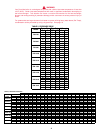
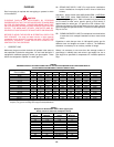
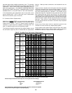
To determine the size of each section of gas piping in a system
within the range of table 4 proceed as follows:
• Determine the gas demand of each appliance to be attached to
the piping system. When table 4 is to be used to select the
piping size, calculate the gas demand in terms of cubic feet per
hour for each piping system outlet. The gas demand for an
appliance can be found by dividing its heat input rate by the
gas’s heating value.
• Obtain or determine the length of piping from the gas meter or
service regulator to the appliance(s).
• In table 1, select the row showing the distance to the most remote
outlet or the next longer distance if the table does not give the
exact length. This is the only distance used in determining the
size of any section of gas piping. If the gravity factor is to be
applied, the values in the selected row of table 4 are multiplied
by the appropriate multiplier from table 5.
• Total the gas demands of all appliances on the piping system.
Enter table 4, on the left hand side, at the row equal to or just
exceeding the distance to the most remote outlet. Select the
pipe size in the row with a capacity equal to or just exceeding
the total gas demand. This is the required main gas supply line
size leading away from the gas meter or regulator. To determine
the pipe size required for each branch outlet leading away from
the main supply line, determine the gas demand for that outlet.
Enter table 4 on the same row, and select the branch pipe size
for a capacity equal to or just exceeding the demand at that
outlet. The main line can be resized for a lesser capacity after
each branch outlet, since the gas demand is reduced. Total the
gas demands of all remaining appliances branching off
downstream on the main gas line. Re-enter table 4 in the same
row and select the appropriate pipe size with adequate capacity.
Repeat the branch sizing and main line re-sizing for any
remaining appliances in the system.
EXAMPLE
Job Condition:
Determining the required gas pipe size for a system composed of
two A. O. Smith 720 boilers and two 960 boilers to be installed as
a multiple group, 50 lineal feet from meter. Gas to be used has a
.60 specific gravity and heating value of 1,000 Btu per cubic foot.
Solution:
Two 720 Boilers = 1,440,000 Btuh (422 kw)
Two 960 Boilers = 1,920,000 Btuh (562 kw)
Total Btuh Input = 3,360,000 Btuh = (984 kw)
Total Btuh Input = 3,360,000 Btuh = 3,360 cf/h
Btu per Cubic Foot of Gas 1,000
With a cubic foot per hour demand of 3,360 and with 50 lineal feet
of gas supply line, table 4 shows a pipe size of 3" is required.
NOTE: For other than .60 specific gravity, apply multiplier factor
as shown in table 5.
HIGH ALTITUDE INSTALLATIONS
IN CANADA
Acceptance of these models for use at altitudes above 2000 feet
(610 m) is based on field test of the individual installation by the
provincial/state authority having jurisdiction.
IN THE U.S.A.
WARNING
INSTALLATIONS ABOVE 2000 FEET REQUIRE REPLACEMENT
OF THE BURNER ORIFICES IN ACCORDANCE WITH SECTION
8.1.2 OF THE NATIONAL FUEL GAS CODE (ANSI Z223.1).
FAILURE TO REPLACE THE ORIFICES WILL RESULT IN
IMPROPER AND INEFFICIENT OPERATION OF THE APPLIANCE
RESULTING IN THE PRODUCTION OF INCREASED LEVELS OF
CARBON MONOXIDE GAS IN EXCESS OF SAFE LIMITS WHICH
COULD RESULT IN SERIOUS PERSONAL INJURY OR DEATH.
You should contact your gas supplier for any specific changes which
may be required in your area.
Ratings specified by manufacturers for most boilers apply for
elevations up to 2000 feet (610 m). For elevations above 2000 feet
(610 m) ratings must be reduced by a rate of 4% for each 1000 feet
(305 m) above sea level.
Example: A Dura-Max is rated at 720,000 Btu/hr. (211 kw) input at
sea level. To operate the boiler at 5000 feet (1524 m) it must be
derated by 20% (4% x 5) to a new rating of 576,000 Btu/hr. (169
kw) input.
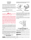
The input reduction is primarily achieved by reducing the size of
the main burner orifices. To do this, the main burner orifices require
replacement with orifices sized for the particular installation
elevation. When ordering, be sure to state the model number and
the altitude of the location where the boiler is being installed.
Upon field deration of the boiler, adjustment to the gas pressure
regulator is required. See CHECKING AND ADJUSTING THE
INPUT in this manual for inlet and manifold pressure requirements.
Also, due to the input rating reduction required at high altitudes,
the output rating of the appliance is also reduced and should be
compensated for in the sizing of the equipment for applications.
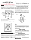
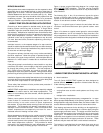
WIRING CONNECTIONS
1. CONVENTIONAL INSTALLATIONS
All electrical work must be electrically bonded to ground in
accordance with the requirements of the authority having jurisdiction
or, in the absence of such requirements, with the National Electrical
Code, ANSI/NFPA 70 and/or the Canadian Electrical Code Part 1,
CSA C22.1, Electrical Code.
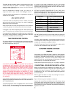
The electrical connections must be made so that the circulator will
operate before the gas valve opens. At no time may the controlling
system allow the burner to fire when there is no water flow through
the boilers.
AN ELECTRICAL GROUND IS REQUIRED TO REDUCE RISK
OF ELECTRIC SHOCK OR POSSIBLE ELECTROCUTION. Make
the ground connection to the screw provided in the electrical supply
junction box on the boiler.