


8
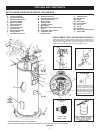
* CAUTION HARNESS HAS 120 VAC. IN OPERATION.
** See “Planning the Vent System,” “Installation of Vent System” and “Condensate Piping” for more information.
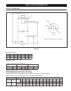
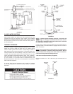
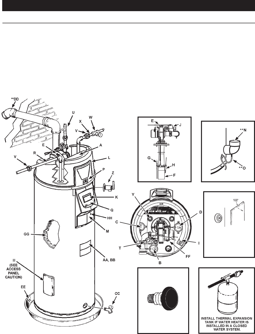
FIGURE 1.
VACUUM RELIEF
VALVE
*INSTALL PER
LOCAL CODES
M Display Enclosure
** N Exhaust Elbow Assembly
** O Condensate Tubing
P Off/On Switch
Q Display Label
R Hot Water Outlet
T Gas Supply
U Main Manual Gas Shutoff Valve
V Union
W Inlet Water Shutoff Valve
X Cold Water Inlet
Y Inlet Dip Tube
GET TO KNOW YOUR WATER HEATER - GAS MODELS
A Control Assembly
B Blocked Inlet Switch
C Blocked Outlet Switch
D Fan Prover Switch
E Blower Assembly
F Burner Assembly
G Flame Sensor
H Hot Surface Igniter
I Junction Box
J Gas Valve Assembly
K Display Board
L Top Plastic Enclosure
Z T/P Relief Valve
AA Rating Plate
BB Labels
CC Drain Valve
** DD Vent Terminal
EE Drain Pan
FF Anode
GG Insulation
HH Upper Temperature Probe
II Access Door
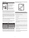
REPLACEMENT PARTS AND DELIMING PRODUCTS
Replacement parts and recommended delimer may be ordered through
authorized servicers or distributors. When ordering parts, provide complete
model and serial numbers (see rating plate), quantity and name of part
desired. Standard hardware items may be purchased locally.
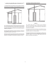
Caution:
This access panel covers
a 2” NPT plug that was required
during the manufacturing of this
water heater. This 2” NPT ange is
not a cleanout tting, removing the
2” NPT plug and using this tting as a
cleanout could void your warranty.
ACCESS PANEL
FEATURES AND COMPONENTS