


21
PVC Materials should use ASTM D-2564 Grade Cement; CPVC
Materials should use ASTM F-493 Grade Cement and ABS
Materials should use ASTM D-2235 Grade Cement.
If the water heater is being installed as a replacement for an
existing power vented heater in pre-existing venting, a thorough
inspection of existing venting system must be performed prior
to any installation work. Verify that correct material as detailed
above has been used, and that the minimum or maximum vent
lengths and terminal location as detailed in this manual have been
met. Carefully inspect the entire venting system for any signs of
cracks or fractures, particularly at joints between elbows and
other ttings and straight runs of vent pipe. Check system for signs
of sagging or other stresses in joints as a result of misalignment
of any components in the system. If any of these conditions are
found, they must be corrected in accordance with the venting
instructions in this manual before completing installation and
putting the water heater into service.
NOTE: For water heaters in locations with high ambient
temperatures (above 100°F) it is recommended that CPVC or
ABS pipe and ttings be used.
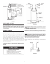
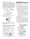
4. All vent (exhaust) pipes must be pitched a minimum of a
1/4” per foot back to the water heater to allow drainage of
condensation.
INSTALLATION OF VENT SYSTEM
Before beginning installation of piping system thoroughly read the
section of this manual VENT PIPE PREPARATION.
If you are installing your system so that it vents through roof,
please refer to section titled INSTALLATION OF VERTICAL VENT
SYSTEM.
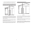
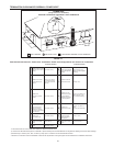
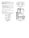
VENT TERMINAL INSTALLATION, SIDEWALL
1. Install the vent terminal by using the cover plate as a template
to mark the hole for the vent pipe to pass through the wall.
BEWARE OF CONCEALED WIRING AND PIPING INSIDE THE
WALL.
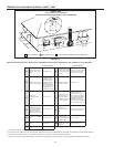
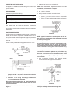
2. If the Vent Terminal is being installed on the outside of a nished
wall, it may be easier to mark both the inside and outside wall.
Align the holes by drilling a hole through the center of the
template from the inside through to the outside. The template
can now be positioned on the outside wall using the drilled hole
as a centering point for the template.
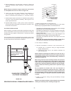
3. A) MASONRY SIDE WALLS
Chisel an opening approximately one half inch (1.3 cm) larger
than the marked circle.
B) WOODEN SIDE WALLS
Drill a pilot hole approximately one quarter inch (0.64 cm) outside
of the marked circle. This pilot hole is used as a starting point
for a saws-all or sabre saw blade. Cut around the marked circle
staying approximately one quarter inch (0.64 cm) outside of the
line. (This will allow the vent to easily slide through the opening.
The resulting gap will be covered up by the Vent Terminal cover
plate.) Repeat this step on inside wall if necessary.