


20
VENTING
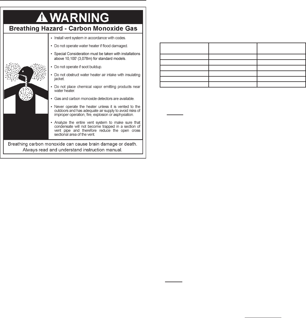
Never operate the water heater unless it is vented to the outdoors.
The instructions in this section of the manual must be followed
to avoid choked combustion or recirculation of ue gases. Such
conditions cause sooting of the combustion chamber, burners and
ue tubes and creates a risk of asphyxiation.
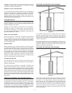
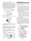
VENT PIPE TERMINATION
The rst step is to determine where the vent pipe will terminate. See
Figures 15, 16, and 17. The vent may terminate through a sidewall
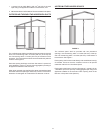
as shown in Figures 15 and 16 or through the roof as shown in
Figures 17 and 18.
The vent system must terminate so that proper clearances are
maintained as cited in local codes or the current edition of the
National Fuel Gas Code, (ANSI Z223.1, 12.9.1 through 12.9.4).
See Figures 13 and 14.
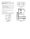
Instructions on proper installation through a sidewall are provided
in Figures 15A, 15B, 15C, and 16.
Plan the vent system layout so that proper clearances are maintained
from plumbing and wiring.
Vent pipes serving power vented appliances are classied by
building codes as “vent connectors”. Required clearances from
combustible materials must be provided in accordance with
information in this manual under FACTS TO CONSIDER ABOUT
LOCATION and INSTALLING THE WATER HEATER, and with the
National Fuel Gas Code and local codes.
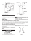
PLANNING THE VENT SYSTEM
Plan the route of the vent system from the exhaust elbow to the
planned location of the vent terminal.
1. Layout total vent system to use a minimum of vent pipe and elbows.
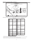
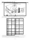
2. This water heater is capable of venting ue gases equivalent to
45’ (13.7 m) of 2” pipe, 128’ (39 m) of 3” pipe as listed in Table 2.
Table 2
Number of
90° Elbows
2” Maximum
Pipe - ft. (m)
3” Maximum
Pipe - ft. (m)
1 40 (12.19) 120 (36.57)
2 35 (10.66) 115 (35.05)
3 30 (9.14) 110 (33.52)
4 25 (7.62) 105 (32)
5 20 (6.09) 100 (30.48)
6 15 (4.57) 95 (28.95)
The minimum vent length for each pipe size is one 90° plus 2’ (61
cm) of straight pipe and the appropriate termination.
NOTE: The equivalent feet (m) of pipe listed above are
exclusive of the termination. That is, the termination, with
an installed screen, is assumed to be in the system and the
remainder of the system must not exceed the lengths discussed
above.
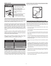
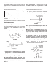
3. The exhaust elbow assembly is designed to accept only straight
sections of 2” pipe. To start, a minimum 2” (5.1cm) maximum
6” long of 2” pipe must be inserted and glued to the exhaust
elbow assembly if utilizing 3” vent pipe. Use the same method
with the blower inlet if a direct vent conguration is utilized.
If using 2” inch vent pipe:
A minimum of 2” (5.1cm) diameter vent pipe must be attached
to the exhaust elbow assembly. The total system cannot exceed
the lengths discussed above, where each elbow is equal to 5
equivalent feet (1.5m) of straight pipe.
If using 3” inch vent pipe:
Two inches (5.1cm) of 2” pipe must be attached to the exhaust
elbow assembly before adding a reducer to acquire the desired
pipe diameter. An appropriately sized 45 degree elbow (supplied
locally-a schedule 40 DWV) vent terminal must be obtained with
an equivalent screen (supplied in vent kit). The total system
cannot exceed the equivalent pipe lengths discussed above
where each elbow is equal to 5 feet (1.5m) of straight pipe (3”
vent pipe).
NOTE: This unit can be vented with PVC pipe materials (DWV
ASTM-D2665 or CSA B181.2; Schedule 40, 80, 120 ASTM-D1785
or CSA B137.3; or SDR Series ASTM-D2241 or CSA B137.3), CPVC
pipe materials (CPVC41 ASTM-D2846 or CSA B137.6; Schedule
40, 80 ASTM-F441 or CSA B137.6; or SDR Series ASTM-F442),
ABS pipe materials (Schedule 40 DWV ASTM-D2661 or CSA
B181.1. The ttings, other than the TERMINATION should be
equivalent to PVC-DWV ttings meeting ASTM D-2665 (Use
CPVC ttings, ASTM F-438 for CPVC pipe and ABS ttings, ASTM
D-2661/3311 for ABS pipe). If CPVC or ABS pipe and ttings are
used, then proper cement must be used for all joints, including
joining the pipe to Termination (PVC Material). If local codes do
not allow the use of the PVC termination when a material other
than PVC is used for venting, then an equivalent tting of that
material may be substituted if the screen in the PVC terminal is
removed and inserted into the new tting.