


19
HIGH ALTITUDE INSTALLATIONS
This high efciency water heater is certied for use without
modication for an altitude of 10,000 feet (3,079 meters). Consult
the factory for installation at altitudes over 10,100 feet (3,079m).
Some gas utility companies derate their gas for altitude, making
it unnecessary to install high altitude orices. Call the local gas or
utility company to verify BTU content.
Due to the input ration reduction at high altitudes, the output rating
of the appliance is also reduced and should be compensated for in
the sizing of the equipment for applications.
Use pipe joint compound or teon tape marked as being resistant
to the action of petroleum [Propane (L.P.)] gases.
The appliance and its gas connection must be leak tested before
placing the appliance in operation.
The appliance and its individual Shut-off valve shall be disconnected
from the gas supply piping system during any pressure testing of
that system at test pressures in excess of 1/2 pound per square
inch (3.5 kPa). It shall be isolated from the gas supply piping system
by closing its individual manual Shut-off valve during any pressure
testing of the gas supply piping system at test pressures equal to
or less than 1/2 pound per square inch (3.5 kPa).
IMPORTANT: MAKE SURE THE GAS LINE IS PIPED IN WITH
HARD PIPE. AVOID FLEX LINE CONSTRUCTION FOR GAS DUE
TO POSSIBLE GAS FLOW PROBLEMS.
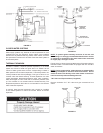
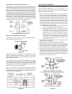
SEDIMENT TRAPS
A sediment trap shall be installed as close to the gas inlet of the
water heater as practical at the time of water heater installation.
The sediment trap shall be either a tee tting with a capped nipple
in the bottom outlet or other device recognized as an effective
sediment trap.
Contaminants in the gas lines may cause improper operation of
the gas control valve that may result in re or explosion. Before
attaching the gas line be sure that all gas pipe is clean on the
inside. To trap any dirt or foreign material in the gas supply line, a
drip leg (sometimes called a sediment trap) must be incorporated
in the piping. The drip leg must be readily accessible. Install in
accordance with the “Gas Piping” section. Refer to the current
edition of the National Fuel Gas Code (ANSI Z223.1/NFPA 54).
FILLING THE WATER HEATER
Never use this water heater unless it is completely full of water.
To prevent damage to the tank, the tank must be lled with water.
Water must ow from the hot water faucet before turning “ON” gas
to the water heater.
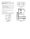
To ll the water heater with water:
1. Close the water heater drain valve by turning the handle to the
right (clockwise). The drain valve is on the lower front of the
water heater.
2. Open the cold water supply valve to the water heater.
NOTE: The cold water supply valve must be left open when
the water heater is in use.
3. To insure complete lling of the tank, allow air to exit by opening
the nearest hot water faucet. Allow water to run until a constant
ow is obtained. This will let air out of the water heater and the
piping.
4. Check all water piping and connections for leaks. Repair as
needed.