


28
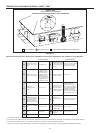
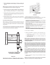
5. Secure assembly to roof structure as shown in Figure 23
using field supplied metal strapping or equivalent support
material.
NOTE: Ensure termination height is above the roof surface
or anticipated snow level as shown in Figure 23.
6. Install rain cap and small diameter pipe assembly in
roof penetration assembly, Ensure small diameter
pipe is cemented and bottomed in Y concentric fitting.
7. Cement water heater combustion air intake and vent pipes to
concentric vent termination assembly. See Figure 23 for
proper pipe attachment.
8. Operate heater through 1 heat cycle to ensure combustion
air and vent pipes are properly connected to concentric vent
termination connections.
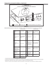
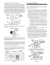
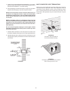
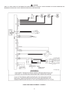
FLAT ROOF INSTALLATION
When installing a concentric termination vertically through a flat
roof, the termination’s vent cap must be a minimum of 10 feet (3
m) away from any parapet, vertical wall or structure as shown
in Figure 23A.
If this required 10 foot (3 m) distance to a parapet, vertical wall
or structure cannot be maintained, standard terminations must
be used. See Vertical Termination Installation.
CONCENTRIC TERMINATION(S)
MUST BE A MINIMUM OF 10 FEET
(3 m) AWAY FROM ANY PARAPET,
VERTICAL WALL OR
STRUCTURE.
CONCENTRIC TERMINATION
FLAT ROOF CLEARANCE
FIGURE 23A.
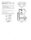
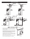
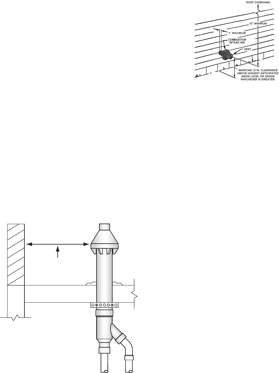
PROCEDURE 2 SIDE WALL TERMINATION, SEE FIGURE 24.
FIGURE 24.
1. Determine best location for termination kit.
NOTE: Consideration for the following should be used when
determining an appropriate location for the termination kit:
• Termination kit positioned where the vent vapors will not damage
plants/shrubs or air conditioning equipment.
• Termination kit positioned so it will not be affected by wind eddy
that may allow recirculation of combustion products, or airborne
leaves, or light snow.
• Termination kit positioned where it will not get damaged or be
subjected to foreign objects, such as stones, balls, etc.
• Termination kit positioned where the vent vapors will not be
objectionable.
NOTE: See the venting information (starting on page 20) in
this manual for additional vent location requirements.
2. Cut 1 hole (5 in. diameter)
3. Partially assemble concentric vent termination kit.
a) Cement the Y concentric fitting to larger diameter
kit pipe, see Figure 19.
b) Cement the rain cap to the smaller diameter kit
pipe, see Figure 22.
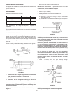
NOTE: Instead of cementing the smaller pipe to the rain cap, a
eld-supplied stainless steel screw may be used to secure the
2 components together when eld disassembly is desired for
cleaning, see Figure 22.
When using alternate screw assembly method, drill clearance
hole in rain cap and pilot hole in vent pipe for screw being
used. Failure to drill adequate holes may cause cracking of PVC
components, allowing combustion products to be recirculated.
Failure to follow this warning could result in personal injury
or death.
Do not operate the heater with rain cap removed or
recirculation of combustion products may occur. Water may
also collect inside larger combustion-air pipe and flow to the
burner enclosure. Failure to follow this warning could result
in product damage or improper operation, personal injury
or death.
4. Install Y concentric fitting and pipe assembly through
structure’s hole.
NOTE: Do not allow insulation or other materials to accumulate
inside pipe assembly when installing through hole.